|
| An introduction to using the IMS B419 graphics TRAM _____________________________________________________________________ |
| Ian Bennett Graphics Department Bristol February 1990 |
This text is intended to help the first time user of the IMS B419 understand how to write a graphics program to execute on the graphics TRAM. It will also be useful to users of the IMS G300 in general, as many routines will be similar, if not identical, to those included here, on other IMS G300 based video display systems. There are several initialisation tasks that a program must achieve, using memory mapped variables, before the screen memory contents will be displayed on the output display device. The jumper settings on the TRAM are explained for different operating modes. Several more advanced topics are also discussed, with extensive examples given in the text. These examples and other useful demonstration programs are available from your local INMOS sales outlet.
Programming examples are given in occam [1], with some INMOS Parallel C equivalents given in section 20. Clearly the language used could be occam, C, FORTRAN, PASCAL, or ADA or some other language supported by a transputer compiler (perhaps FORTH, BASIC, LISP, or PROLOG). The principles of operation remain the same, however, whatever programming language is used. The example occam programs have been written using release 2 of the INMOS Transputer Development System (TDS) [2], the example parallel C programs [3] were written using the INMOS C Compiler (ICC) [4], run in conjunction with the INMOS Toolset [5], and the author assumes some familiarity with these.
A recent addition to the INMOS range of TRAnsputer Modules (TRAMs) is the IMS B419 graphics TRAM, providing a complete high performance graphics subsystem on a single 6.5” by 3.5” (size 6) printed circuit board.
Incorporated on the IMS B419 is an IMS T800 floating point transputer running at 20 MHz, an IMS G300 Colour Video Controller, 2 Mbyte 200 ns cycle DRAM, and 2 Mbyte 200 ns cycle dual port VRAM. A jumper option on the IMS B419 allows the VRAM to be used as contiguous program memory, if required.
The IMS B419 enables a wide range of arbitrary display resolutions to be supported, from VGA, 640 by 480 (30 MHz)1 to 1280 by 1024 (110 MHz), using 8 bits per pixel (or with the latest version, the IMS G300B, 1, 2, 4, or 8 bpp). With resolutions of up to 1024 by 1024, multiple bitmaps can be supported. This enables frame flipping during frame flyback for animation purposes and elimination of disturbing visual effects during image updates.
The 20 MHz IMS T800 processor provides 10 MIPS, and 1.5 MFLOPS sustained performance, and has 4 Kbytes of fast internal SRAM for critical sections of code and frequently accessed variables. The IMS T800 can perform two dimensional block moves, in one of three modes, move, draw and clip [6], allowing windowing, panning, scrolling, character drawing, and screen block updating. Panning and scrolling can be performed more efficiently by the IMS G300 CVC, by modifying the Top of Screen register, depending upon the memory and screen dimensions.
The IMS T800 controls the IMS G300 CVC, programming the registers and colour palette, and enabling the video timing generator, and has full access to the bitmap. The phase-locked loop oscillator of the IMS G300 CVC can be programmed to integer multiples of either the processor input clock or a clock module plugged onto the board. This allows multiples of frequencies other than the 5 MHz processor clock to be obtained. The IMS T800 can also control a subsystem of transputer boards, using the hierarchical reset, analyse and error control signals.
The IMS B419 may be used as the host transputer board, running the TDS or some other programming environment, or as a target board, communicating with the host transputer board via a high speed communication link.
If the IMS B419 is being used as the host board, then programs can be compiled and executed as EXEs under TDS, or as PROGRAMS, extracted and written in host format using the TDS filer utilities, then executed from DOS using the normal INMOS Toolset Utilities.
Alternatively, if the graphics TRAM is being used as a target board, then programs are compiled as PROGRAMS under TDS, and loaded onto the target board using the TDS utilities, or using ISKIP in the Toolset Utilities.
The appropriate programming environment documentation should be consulted if the reader has any doubt about executing programs on a transputer board.
The IMS B419 has five jumper positions, JP1-JP5. Their functions are listed below [7].
| |||||||||||||||||||||
To enable the IMS G300 phase locked loop, jumper 1 is not installed. It may be noted here that if an IMS G300B is being used, the phase locked loop can be enabled and disabled by writing bit 5 high or low respectively in the Boot Location (Adding 3210 to the PLL multiplier factor). This cannot be performed with the IMS G300A, so the jumper must be installed if required.
Jumpers 2 and 3 are mutually exclusive, in that either one should be installed, or the other, but not both. With the IMS G300A, jumper 2 selects the on-board oscillator module and jumper 3 selects an off-board frequency source. The phase locked loop must be disabled in order to use either of these frequency sources.
If an IMS G300B is being used, the function of the SMB connector 6 will change from External Pixel Clock In to CBlank Input/Output. An off board frequency source can no longer be used. Selection can be made between the system clock and the oscillator module clock using the Oscillator Select Register (and no jumper changes). Neither JP2 or JP3 are required for this. Setting the Oscillator Select Register bit 0 low causes the IMS T800 system clock (5 MHz) to be used as the IMS G300 pixel clock in. If bit 0 is set high, the IMS G300B pixel clock input is from the on-board oscillator module. The phase locked loop must be disabled when using the oscillator module. jumper 3 should be installed in order to use CBlank input/output.
The VRAM memory can be selected to start at the end of the DRAM (contiguous) (#80200000) by installing Jumper 4 or at a different address (non-contiguous) (#C0000000) by installing jumper 5. These two jumpers are mutually exclusive, and exactly one of them should be connected. This allows applications to expand, utilising VRAM as program and data area in addition to DRAM.
The addresses of the relevant IMS B419 components is shown below [7, 8].
|
The VRAM always appears to start at #00000000 to the IMS G300, whether it appears contiguous or noncontiguous (with the DRAM) to the IMS T800. The IMS G300 registers and palette are indexed on word address boundaries from the G300 register base as below:
|
In order to program the IMS G300, an INT array of size #1BF can be placed at the IMS G300 register base, and the individual registers accessed from within this. Note that in occam, the occam address must be used for the placement, this being word addressed from 0, as compared with the hardware byte address being addressed from #80000000. To calculate an occam address from a hardware address on an IMS T800 [9]:
occam.address := ((hardware.address >> 2) -
(MOSTNEG INT >> 2)) /\ #3FFFFFFF |
Individual INT variables and channels can be declared and placed at the appropriate addresses, in order to control subsystems, reset and control the G300, and access the Event input signal (Frame Flyback).
A complete example program to draw a box on the screen is shown below. This demonstrates many of the requirements of a program executing on the IMS 8419.
VAL g300.register.base IS #30000000:
VAL vram.base IS #10000000: VAL INT boot.location IS #1A0: VAL INT top.of.screen IS #180: VAL INT control.register IS #160: VAL INT mask.register IS #140: VAL INT half.sync IS #121: VAL INT back.porch IS #122: VAL INT display IS #123: VAL INT short.display IS #124: VAL INT broad.pulse IS #125: VAL INT v.sync IS #126: VAL INT v.blank IS #127: VAL INT v.display IS #128: VAL INT line.time IS #129: VAL INT line.start IS #12A: VAL INT mem.init IS #12B: VAL INT transfer.delay IS #12C: VAL INT colour.palette IS #000: VAL width IS 1024 : VAL height IS 1024 : [#1BF] INT registers: PLACE registers AT g300.register.base: [height * width] BYTE screen : PLACE screen AT vram.base: BYTE g300.reset.reg : PLACE g300.reset.reg AT #2000003C : BYTE g300.clock.sel.reg : PLACE g300.clock.sel.reg AT #2000003D : PROC setColour ( VAL INT colour, r, g, b ) SEQ registers [colour] := (r \/ (g << 8)) \/ (b << 16) : ... PROC set. colour.spectrum.palette () PROC init.display() VAL prog.regs IS [half.sync, back.porch, display, short.display, broad.pulse, v.sync, v.blank, v.display, line.time, line.start, mem.init, transfer.delay, mask.register]: VAL prog.vals IS [11, --half sync 60, --back porch 256, --display 82, --short display 164, --broad pulse 8, --v sync 70, --v blank 2048, --v display 348, --line time 0, --line start 494, --mem init 18, --transfer delay 255]: --mask register SEQ g300.reset.reg := 1 (BYTE) -- reset IMS G300 g300.reset.reg := 0 (BYTE) registers[boot.location] := 17 registers[control.register] := 0 SEQ i = 0 FOR SIZE prog.regs registers[prog.regs[i]] := prog.vals[i] registers[control.register] := 1 -- start VTG, mode 1 : PROC cls ([] BYTE screen, VAL INT colour) VAL screen.size.m.4 IS (SIZE screen) - 4 SEQ screen[0] := BYTE colour screen[1] := BYTE colour screen[2] := BYTE colour screen[3] := BYTE colour [screen FROM 4 FOR screen.size.m.4] := [screen FROM 0 FOR screen.size.m.4] : -- main program starts here INT offset : VAL start.x IS 100 : VAL start.y IS 200 : VAL length.x IS 200 : VAL length.y IS 100 : VAL colour IS 255 : SEQ cls(screen, 0) init.display() set.colour.spectrum.palette () offset := (start.y TIMES width) + start.x SEQ col = 0 FOR length.x screen [offset + col] := BYTE colour SEQ row = 0 FOR length.y - 1 SEQ [screen FROM offset + width FOR length.x] := [screen FROM offset FOR length.x] offset := offset + width |
The IMS G300 is first reset, although this may not be required if the transputer has been reset prior to booting, as the IMS G300 will also have been reset. The Control Register is initialised, then the phase locked loop clock multiplier value is written, and the remaining registers written with their respective values.
The 256 locations of the colour palette are programmed using the procedure setColour. The setColour procedure makes a 24 bit colour value by shifting the red, green, and blue 8 bit components to the correct places within the 32 bit word. This is then written at the address specified by colour in the colour palette.
In the example program a colour spectrum palette is programmed, but the procedure for this has been omitted for clarity; it can be found in section 19.1.
The program above has executed on an IMS B419 as shown, and draws a white box 100 by 200 on the screen. It may be interesting to note a couple of techniques used in the coding. The screen is cleared before the VTG is enabled, to avoid the random power up state of the VRAMs being instantaneously displayed. The cls procedure clears the screen using the most efficient method possible, but does require that alias, usage and range checking are disabled to compile and run. Other techniques that are almost as fast, but allow these checks to be performed can be found in [9]. Note that these techniques may also be performed with two dimensional screens, using a single dimensional retyped screen within the procedure.
Other efficient techniques shown include the use of the fast unchecked multiplier TIMES for multiplying by the screen width. This takes 15 cycles using a screen width of 1024 or 210, and is faster than using the multiplication operator , which takes 39 cycles [10]. Use could have been made of the left shift operation << 10 to multiply by 1024, but as this takes 13 cycles, little is lost to keep the multiplication general, for any screen width.
Use is made of a variable, offset pointing to the start position on the last screen line. This offset is incremented by the screen width after each line write to the screen. This is more efficient than computing the screen offset each time.
A single dimensional screen is used, instead of a two dimensional screen, for reasons of efficiency. Using an incrementing offset, as discussed above, is faster than using X,Y addressing with a two dimensional screen. Referring to the two techniques shown in (a) and (b) below, the X,Y addressing performance of (a) is equivalent to the alternative technique (b), but both are slower than the technique implemented using an offset in (c):
A functionally equivalent Parallel C version of this simple example is shown in section 20.1.
The theory of line drawing is extensively discussed elsewhere [11, 12]. The most efficient of the algorithms published is that of Bresenham [13]. This uses incremental techniques and an error term, adding 1 to the driving axis, and conditionally adding +/- 1 to the other axis. The use of a fixed point slope value is discussed in [12], and the author has found that the performance is approximately the same as using a floating point value on the IMS T800.
The author has developed a significantly faster routine, however, based on Bresenhams, but over 50% faster (when implemented on a transputer). This takes advantage of several performance enhancement techniques, and implementational specifics on transputers. No floating point is used, so the execution speed should be comparable on IMS T2XX and IMS T4XX devices to that on IMS T8XX devices (disregarding different memory cycle times).
The complete procedure is listed in section 19.3, for both driving axes. Fold creases have been left in, to allow the code to be refolded if desired. Some inner loop unrolling has been implemented, which would make the listing unwieldy, so the latter three steps of the unrolled inner loops have been left folded up. They are each identical to the first step of the loop. This routine has been measured on the IMS B419 to plot a line from (0,0) to (1279,1023) in 2473μs. This equals 1280 pixels in 2473μs, or 518K pixels per second, or 1.93μs per pixel.
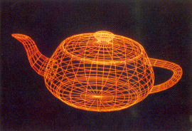
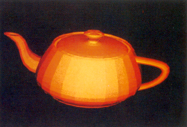
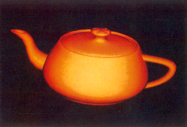
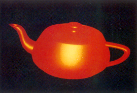
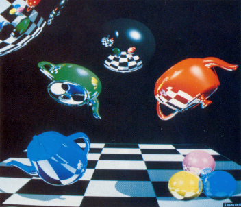
The IMS B419 is well suited for 3-D modelling and manipulation, using realistic shading techniques. The IMS T800 can perform 55,000 3-D floating point matrix transforms per second (1 by 4 multiplied by 4 by 4), allowing models to be translated, rotated, and scaled at high speed. Clearly the complexity of the model and the transformations and manipulations that are performed on it will affect the speed of response. Simple 3-D models can be rotated (x, y, z) and displayed using flat or Gouraud shading (with hidden surface removal) in real time. Rendering techniques including Wireframe, and Flat, Gouraud and Phong shading have all been implemented on the IMS B419, using various models including the standard Utah Teapot (using a polygonal mesh surface approximation derived from the original Bezier Patch representation) (see figures 1a-d).
|
The IMS B419 can also be used to perform more realistic rendering, such as Ray Tracing [14, 15]. Ray tracing is one of the most realistic techniques available today (as well as radiosity), but is an extremely computationally intensive task. Extra transputer modules can be connected to the IMS B419 links, to provide more processing power.
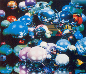
An example ray traced image is shown in figure 2a. This image, titled ’Chaos’ has approximately 150 assorted objects of random proportions and colours, mostly spheres, but also includes cones, cylinders, and disks. There is also a mirror on the ’floor’. This image took approximately one hour to compute (with anti aliasing) on a pipeline of nine IMS T800 based IMS B404 transputer modules. A more computationally intensive image is shown in figure 2b. This is a ray traced image of three ’dancing’ teapots. Solving the intersection of a ray with the curved 3-D surfaces (Bezier Patches) is complex and non-trivial, and involves recursion. It took ten hours to compute ’Waltz’ on the pipeline of nine IMS T800 transputers (again with anti aliasing), or approximately 5 ∗ 1011 floating point operations.
|
When writing to the screen in the simple example above, the screen update is very fast. Other screen writing tasks may not be so fast, however, especially when performing polygon shading incorporating hidden surface removal. In order to present a fast and smooth screen update to the user, and hide the screen updating process, screen flipping is often used. The screen that is being updated is not visible to the user until it is complete, whereupon the screens are flipped, and the display is instantaneously updated with the new image. The previously displayed screen can then be updated, without the user seeing it.
The value to write to the Top of Screen register depends upon the size of the screen declared, and which screen array is to be displayed. It is often convenient to declare screens as multidimensional arrays, so that an index into the screen array indexes the appropriate screen. This ensures that the screens used are contiguous (useful for scrolling), no VRAM is wasted, and a variable (visible. screen in the example below) can be used in the user program to write directly to either the visible screen, or a non visible screen. Many screens can be used, by declaring the screen array appropriately, and cycling through the allowable values for the variable visible. screen. The formula for the Top of Screen register value is:
VAL screen.flip.value IS
((width * height) * (visible.screen * 4)) / 2048 : |
The screen size must be a multiple of 2048, however, due to the VRAM and memory architecture on the IMS B419.
Screen flipping can be performed at any time, by writing to the Top of Screen register in the IMS G300, but this can cause a glitch to appear on the display. If it is done during the frame flyback time, however, then an imperceptible swap is obtained, with no lines or other noise being displayed. This can easily be achieved on the IMS B419 using the procedures and techniques below, making use of the frame flyback signal connected to the Event input on the IMS T800 [7].
PROC EventHandler ( CHAN OF ANY EventReq, EventAck, stop )
CHAN OF ANY Event : PLACE Event AT 8 : INT any : BOOL running : SEQ running := TRUE WHILE running PRI ALT Event ? any SKIP ALT EventReq ? any SEQ Event ? any EventAck ! any stop ? any running := FALSE : [2][width * height] BYTE screen.12 : -- two screens INT visible.screen : PROC toggle.screen (INT visible.screen) SEQ visible.screen := 1 - visible.screen VAL screen.flip.value IS ((width TIMES height) TIMES (visible.screen << 2)) >> 11 : SEQ registers [ top.of.screen ] := screen.flip.value : CHAN OF ANY EventReq, EventAck, stop : PRI PAR EventHandler ( EventReq, EventAck, stop ) {{{ user process visible.screen := 0 ... user code ... write to screen[1-visible.screen] EventReq ! any -- wait for frame flyback EventAck ? any -- frame flyback signal toggle.screen (visible.screen) -- flip screens ... user code stop ! 1 -- terminate the EventHandler process }}} |
A process EventHandler executes at high priority in parallel with the user process, continually receiving event inputs that signify frame flyback times. This process will consume approximately 1% of the processor resource. When the user wants to synchronise with the frame flyback time, an output is made to the EventHandler process, which, on the next event input, outputs an acknowledge to the user process. The Top of Screen register in the IMS G300 CVC can then be updated with the new value.
The channel stop is included to allow the user process to terminate the parallel EventHandler process, if required. This is generally only necessary if executing the program from within the host programming environment. The user process must output to this channel before terminating, as otherwise the EventHandler process would continue executing, thereby locking out the host environment.
A functionally equivalent Parallel C version of the EventHandler process, together with the required user synchronisation commands, is listed in section 20.2.
Simple animation can be performed on the IMS B419. This could be achieved using the graphics TRAM as an output display driver being supplied with display data by many extra processors connected via the four high speed links. The multi-processor system would perform the model movement and shading calculations, and could feed pixel data to the IMS B419. Using 8 bits per pixel and 512 by 512 display resolution, a theoretical maximum speed would be approximately 24 frames per second. This assumes that the limiting factor would be the speed of the four links, and not the external model manipulation and shading computation. This is unfortunately beyond the scope of this text.
This section explores the possibilities for animation using only the IMS B419. The Graphics TRAM has 2 Mbyte of VRAM and 2 Mbyte of DRAM. If a screen display resolution of 512 by 512 with 8 bits per pixel is used (256 Kbytes per screen), a user program can declare 16 screen arrays, 8 placed in VRAM, and 8 placed in DRAM. Allowing 256 Kbytes for the user program code and variables, this reduces to 7 screen arrays in DRAM. These screens might be declared, in occam as below:
[8] [512 * 512] BYTE vram.screens :
PLACE vram.screens AT vram.base : spare.screen IS vram.screens [7] : [7] [512 * 512] BYTE dram.screens : PLACE dram.screens IN VECSPACE : |
If a model is rendered into each of the first 7 VRAM screens and the 7 DRAM screens (the last VRAM screen is used as a spare screen), with some form of cumulative movement, rotation or distortion being applied to the model before each rendering, then these 14 frames can easily be cycled through on the display monitor. One way of performing this is shown below:
VAL screen.size IS 512 * 512 :
PROC set.screen (VAL INT visible.screen) SEQ ... synchronise with frame flyback registers [ top.of.screen ] := (screen.size TIMES (visible.screen << 2)) >> 11 : SEQ set.screen (0) -- display vram.screens [0] {{{ render model start position into first screen cls (vram.screens [0], black) ... render model into vram.screens [0] }}} {{{ render model into other 13 screens spare.screen := vram.screens [0] -- save first screen SEQ i = 1 FOR 6 -- prepare VRAM screens, done 1st SEQ ... move / rotate / distort model cls (vram.screens [0], black) ... render model into vram.screens [0] vram.screens [i] := vram.screens [0] -- save into appropriate scrn SEQ i = 0 FOR 7 -- prepare DRAM screens SEQ ... move / rotate / distort model cls (vram.screens [0], black) ... render model into vram.screens [0] dram.screens [i] := vram.screens [0] -- save into appropriate screen vram.screens [0] := spare.screen -- retrieve 1st screen }}} {{{ cycle through the 14 frames WHILE running SEQ i = 0 FOR 7 SEQ set.screen ((i + 1) \ 7) -- select scrn to disp spare.screen := vram.screens [i] -- \ vram.screens [i] := -- \ dram.screens [i] -- } swap last displayed scrn dram.screens [i] := -- / spare.screen -- / }}} |
Referring to the above occam listing, the model is always rendered into the displayed screen, vram.screens [0], so that the progress can be monitored. This is then copied into the appropriate VRAM or DRAM screen array. The model is then moved, distorted, or rotated by 1/14 of the total amount desired (for rotation, this could be 360/14 degrees so as to return to the start position after 14 frames). The 7 VRAM screens are then displayed in turn, with the last displayed VRAM screen being swapped with the appropriate DRAM screen each time. The display cycle loop is then repeated, with the former DRAM screen frames now in VRAM, and each of these are displayed once, again swapping over the last displayed frame with that in DRAM. Note that this cycling loop must repeat twice for the 14 frames to be displayed once each. This is necessary because whilst the IMS G300 can display any area of VRAM (by setting Top of Screen appropriately), it cannot display the contents of DRAM, as DRAM does not have the dual port shift register access, so these must be swapped, one at a time, with the VRAM frames).
A demonstration of this technique has been written, which renders a Gouraud shaded Utah Teapot into the 14 screens. The Teapot was rotated about one of the X, Y or Z axes 360/14 degrees each time, then transformed with a view transformation matrix (for perspective) before being rendered (with hidden surface removal). The final effect is quite startling, as although only 14 frames are being displayed, the eye is fooled into interpolating the movement between successive frames, and effectively smoothes the movement. The 14 frames are displayed in approximately 2 seconds, this being determined by the time taken to swap the previous frame over, from VRAM to DRAM via the spare screen.
Clearly this technique does not demonstrate elaborate animation, as only 14 frames are being used, and the content of those frames is not being altered dynamically, but the potential of the IMS B419 for this type of task is apparent.
Consider the use of the IMS G300B with 4, 2 or 1 bits per pixel. The use of a lower number of bits per pixel, still at 512 by 512 resolution, decreases the amount of memory required for each frame, so more frames can be declared and used, as shown below.
|
In the extreme case, using 1 bit per pixel, 128 frames can be declared in memory, although less than this number could be used for the animation due to the spare screen needed and the requirements of the user program code and variable space, as discussed above. Even so, say 125 were used (allowing a spare VRAM screen and 64 Kbytes for code and variables) then this could allow an animation sequence of 20 frames per second, lasting for over six seconds. Note that the frame cycling loop would execute faster, in inverse proportion to the size of the frame being used. This may need to be kept to the desirable frame rate by the use of a timed delay. If the ability was added to update non-visible screens, (whilst the screen cycling loop was descheduled waiting for the timed delay to elapse), then quite complex animations could be achieved using only the IMS B419.
The use of 1 bit per pixel in this discussion would seem to limit the number of displayable colours to 2, but whilst this is strictly true for any one frame, it would not necessarily be the case when performing the animation. A simple palette updating procedure could be synchronised to the frame flipping, (as discussed elsewhere in this text) so that the actual 24 bit colour values in the palette addressed by the pixel values could be changed dynamically. The palette could also be altered during the display of each frame, while the screen arrays were being swapped, and/or during the timed delay. This could effectively greatly extend the number of displayable colours during the animation, clearly depending upon the frame cycling rate being used, and the frame rate of the display monitor.
Scrolling and panning may be efficiently performed on the IMS B419 by writing to the IMS G300 Top of Screen register [16].
To perform scrolling, the screen array width must be a multiple of 512, due to the way that the VRAM shift registers are updated on the IMS B419. To scroll the display up by two lines, the Top of Screen register contents must be incremented by four, assuming the screen width is 1024. If the width is 512, the display will scroll by 4 lines. Single line scrolls cannot be performed on the IMS B419 due to the memory organisation and VRAM register length. Clearly decrementing the Top of Screen register contents by four will scroll the screen display down, as long as the register value does not become negative.
Scrolling with a normal screen array will display uninitialised memory. If the screen array is initialised to have more lines than are displayed, however, then the screen may be used as a display window scrolling on a larger than displayed image. Alternatively, a second screen array contiguously placed in memory (or a double screen using a 2-D array) could be scrolled onto the display. This is implemented in the ’Wobbler’ routine (section 12.4).
Incrementing the Top of Screen register by 4096 increments the SAM start address field within the Top of Screen register, and causes the display to pan to the left by four pixels. Clearly decrementing by 4096 will pan to the right, again keeping the register value positive.
Performing panning with a normal wholly displayed screen array achieves a ’pseudo-pan’ or a rotation, with the displayed image wrapping around from one side of the screen to the other, one line above or below. If the screen line length is actually longer than that displayed, however, then the screen can be used as a display window panning on a larger than displayed image. Due to the length of the VRAM shift registers on the IMS B419, the width of the declared screen array must be a multiple of 2048, in order have some non-displayed RAM to pan into. This means that with a screen display of 1024 wide, for example, a screen array of width 2048 must be declared. In this case, Memlnit and TransferDelay must add up to 1024/4 = 256, so Memlnit must be set to 256- TransferDelay, = 238 using the simple example program above. TransferDelay remains unchanged.
Scrolling and panning may be achieved together, incrementing the Top of Screen register fields appropriately. This is best performed during frame flyback time, using the EventHandler process described above. The scrolling and panning actions are summarised below.
| |||||||||||||||||||||
A demonstration routine has been written to demonstrate the scrolling and panning of the display. The routine is self contained, and executes at low priority, in parallel with a user graphics program.
The routine is listed in section 19.4, and essentially scrolls and pans the display continuously, keeping a note of how many lines and pixels have been scrolled and panned. This prevents the value written to the Top of Screen register from becoming negative. Two screens must have been declared, as in section 10 Screen flipping. The routine copies the visible screen to the invisible screen before updating the Top of Screen register, so that scrolls appear to wrap around from the top of the screen to the bottom. Pseudo-pans also cause the display to wrap around the sides of the display.
The effect of the Wobbler, when combined with graphics drawing (and palette cycling) is quite effective and eye catching.
This clearly shows the use of such pan and scroll operations, allowing either the whole display to be moved, almost ’for free’, or to use the display as a window on a larger than displayed image.
Note that a second pair of frame synchronisation channels are used in the Wobbler, and the EventHandler must be modified to cope with these requests in parallel. The standard EventHandler routine (modified for two Event request channel pairs, say) would serve the first active Event request on the next Event input, then wait for the subsequent Event input before serving the second Event request. Clearly this would result in the second process being locked out (and descheduled), until two Event inputs have occurred.
An improved EventHandler routine that can serve n channel pairs (without lockout while waiting for the Event input) is shown in section 19.5. This routine has the advantage that two asynchronous Event requests will both be served on the next Event input, and neither will be forced to wait the extra frame time as discussed above. Note that sometimes it is advantageous however, to only allow one process to access the IMS G300 per frame flyback.
Interesting effects can be obtained by cycling the palette of a displayed image (in mode 1). Performing this, for example, on a Mandelbrot display can yield some spectacular effects.
Fast movement can be achieved with minimal processor loading by palette cycling. This enables the processor to perform other more computationally intensive tasks without affecting the ’background’ movement. This is performed in the examples in mode 1, 8 bits per pixel, but if the latest version of the G300 is used, the G300B, then this could also be performed in mode 1, using 1, 2, 4 or 8 bits per pixel. Palette cycling may also be performed in mode 2 using 24 bits per pixel. In mode 2, the 8 bits per colour are passed through the palette, which can be used for gamma correction, or, in this case, to simulate movement.
A simple example of movement by palette cycling is the ’rotation’ of helicopter blades. Blades are drawn as radial triangular polygons, with each polygon colour value being different, as shown below. Note that various VAL and VAR declarations have been omitted from the example listing for clarity.
poly [0][0] := x0 -- centre of blades
poly [0][1] := y0 VAL theta IS 360.0 (REAL32) / (REAL32 ROUND rotors) : SEQ i = 1 FOR rotors VAL angle IS ((REAL32 ROUND i) * theta) * degrees.to.radians : VAL small.angle IS (theta / 1.1(REAL32)) * degrees.to.radians : INT dx, dy, dx1, dy1 : SEQ dx := INT TRUNC ((SIN (angle)) * radius) dy := INT TRUNC ((COS (angle)) * radius) dx1 := INT TRUNC ((SIN (angle + small.angle)) * radius) dy1 := INT TRUNC ((COS (angle + small.angle)) * radius) poly [1][0] := x0 + dx poly [1][1] := y0 + dy poly [2][0] := x0 + dx1 poly [2][1] := y0 + dy1 fillPoly (3, poly, i, screen[visible.screen], width, height) filledCircle (x0, y0, INT TRUNC (radius / 10.0(REAL32)), 255, width, height, screen (visible. screen]) |
The listing above also shows a red filled circle being drawn at the centre of the blades, in order to hide the quantisation noise due to all the triangles meeting at the centre. Below is an example listing of a routine to initialise and cycle the colour palette. This routine would normally run at high priority, in parallel to the main user code, so that the updating of the colour palette is not timesliced, which would result in the same effect as updating the palette without synchronisation with the frame flyback signal, i.e. noise and streaking at the top of the display. The effect this palette cycling gives is to produce two rotor blades on opposite sides of the rotor, one blue and the other green. The rotor appears to rotate, with the blue and green rotors moving gradually around the centre.
INT i :
[256] INT palette : SEQ SEQ i = 0 FOR 256 SEQ palette[i] := 0 setColour (i, 0, 0, 0) palette [ (rotors / 2) - 1] := #FF0000 -- b palette [ rotors - 1] := #00FF00 -- g palette [((3 * rotors) / 2) - 1] := #FF0000 -- b setColour (255, 255, 0, 0) -- bright red i := 0 WHILE TRUE INT any : SEQ INT any : -- wait for frame flyback SEQ EventReq ! any EventAck ? any [registers FROM 1 FOR rotors] := [palette FROM i FOR rotors] i := (i + 1) \ rotors |
Referring to the listing above, a couple of important points may be noted. The palette is always updated during frame flyback time, to avoid any noise and lines appearing on the screen. The palette is updated with a single slice assignment, rather than individual word assignments, to ensure that the frame flyback time is not exceeded. The number of palette locations used by the movement routine is dependent on the number of rotors declared, where
No of locations used = (3 * rotors) / 2
|
plus one for the centre circle and one for the background colour. If the two blades are drawn with the same colour (white for example), then the number of palette locations can be reduced to
No of locations used = rotors
|
taking advantage of the semicircular symmetry, where rotor blade 1 effectively becomes rotor blade 2 halfway around, and the palette pointer only varied from 0 to rotors / 2.
Clearly the speed of rotation of the rotor is dependent on the number of blades declared, and the frame rate of the screen display being used. Alternatively it is possible to only wait for alternate frame flyback times, thus doubling the speed of rotation, but this tends to yield less aesthetically pleasing results. This is due to the palette being cycled twice per frame, in which case both palette states may not be apparent on the display.
A demonstration program was written using these techniques, yielding two rotors of different sizes and numbers of blades rotating in opposite directions at different speeds, and a continually moving block around the screen border. In addition, to simulate the main task, the entire centre section of the screen was moved gradually up and down, (using a second screen and frame flipping), to yield an eye catching and interesting display.
This demonstration required two asynchronous frame flyback synchronisation in parallel, as in the Scrolling and Panning Wobbler example above, to perform the palette cycling, and the frame flipping. The EventHandler.n process (listed in section 19.5) was thus used, with order two, to perform the dual parallel process frame synchronisation.
Palette cycling can be performed in mode 2, 24 bits per pixel (described below), whereby ’moving’ objects may non-destructively overlap or move over each other, something that is not possible in mode 1. The objects thus overlapping will, of course, be a combination of two or three different shades of colours from red, green and blue, allowing any of the full range of 16 million colours to be displayed.
The IMS B419 may be used in mode 2, allowing full colour 24 bits per pixel displays to be obtained. To achieve this, an external 85-100 MHz signal must be supplied to the external frequency input, or alternatively an 85 MHz oscillator module plugged into the vacant socket on the board, and the phase locked loop disabled by connecting jumper JP1 on the board. The oscillator is selected by removing jumper JP3 and installing J P2.
If the board has an IMS G300B, then the oscillator module can be selected by writing a 1 (BYTE) to the g300. clock. sel.reg. The phase locked loop can be disabled with the IMS G300B by writing a zero to bit location 5 in the Control Register.
The IMS G300 vertical parameters are calculated as in [7, 8], but the horizontal parameters must be calculated differently. These are:
Half Sync
BackPorch Display ShortDisplay BroadPulse LineTime TransferDelay |
Effectively these horizontal parameters are calculated for the horizontal resolution as with the 8 bit mode, but are multiplied by 4. Memlnit is calculated from 512 - the new value of TransferDelay. The Control Register must be set to #101, instead of the normal mode 1 value of #1.
A full set of parameters is given in section 19.2 for full colour mode using an NEC Multisync XL, at 512 by 512 resolution. Note that the parameters shown were generated (by the Parameter Calculation Program - see section 16, Demonstration programs) for a screen of 512 by 512, then the horizontal parameters were multiplied by 4.
When used in mode 2, a screen array must be declared to be of type INT, which yields 24 bits of colour information and 8 bits of (at present) unused data. Bits 0 to 7 are red, bits 8 to 15 are green, and bits 16 to 23 are blue. These can either be accessed by shifting up the bytes (as with procedure setColour above), or retyping a [4] BYTE array onto each INT, and accessing the subscripted elements, [0] = red, [1] = green, and [2] = blue. Alternatively a [] BYTE screen array of four times the screen size could be retyped onto the []INT. screen, or a [] [4] BYTE screen array used.
It should be noted that if an IMS G300B is used in the IMS B419, then the function of the SMB edge connector changes from External Pixel Clock In to CBlank input / output. An external frequency source can no longer be input to the IMS G300B. An oscillator module may still be used, however, to generate particular video frequencies, or for running in mode 2.
A number of demonstration programs have been written, to show the IMS B419 working in mode 2. These are available from your local INMOS sales outlet.
A number of features and enhancements have been incorporated in the latest version of the IMS G300, the IMS G300B [17]. This may be fitted as a direct replacement for the IMS G300A on the IMS B419.
The number of bits per pixel can be 1, 2, 4, or 8 in mode 1. The main use of this is to increase the speed of drawing shapes, PIXBLT operations, and moving (expanding) text to the screen. A demonstration program has been written (adapted from the IMS G300A version of the Random Squares) that switches between the different bits per pixel. This clearly shows the speed of drawing the squares to the screen progressively doubling as the number of bits per pixel is halved. It was found that when using 1 or 2 bits per pixel, the update rate to the screen was so fast that squares were being drawn, and overdrawn, before a complete frame had been displayed on the display.
When using lower numbers of bits per pixel, the little endian convention is adhered to, in terms of bytes and bits. It may be noted that reducing the number of bits per pixel means that pixels cannot be manipulated using BYTE writes, as with 8 bits per pixel. One technique used in the demonstration program is to write multiple pixels using a composed 8 bit colour byte value. This technique would only be used when the number of pixel bits to be written was a multiple of a byte. Clearly the number of pixels written will be:
Number of pixels written := 8 / bits per pixel
|
The colour byte value was constructed using the technique below.
IF
bpp = 8 SKIP bpp = 4 SEQ colour.byte := colour \/ (colour << 4) bpp = 2 SEQ colour.byte := colour \/ (colour << 2) colour.byte := colour.byte \/ (colour.byte << 4) TRUE -- 1 bpp IF colour = 0 colour.byte := 0 TRUE colour.byte := #FF |
Clearly if a read modify write operation is to be performed, using less than 8 bits per pixel, then shift and mask operations will be necessary.
The colour palette will also need to be reprogrammed, when using less than 8 bits per pixel, as this reduces the number of colours that can be displayed on screen at any one time. In 4 bpp mode, palette locations 0 to 15 are used. In 2 bpp mode, palette locations 0 to 3 are used, and in 1 bpp mode only palette locations 0 and 1 are used. All other palette locations are not used in these modes.
To alter the number of bits per pixel, bits 18 and 17 are set appropriately in the IMS G300B Control Register, as shown below.
|
One important point must be noted when changing the number of bits per pixel, in order to keep the memory organisation continuous. Normally, in 8 bits per pixel, the TransferDelay and MemInit sum to the VRAM shift register length (512). With 4 bits per pixel, however, they must sum to twice this value, 1024, as the VRAM register length now corresponds to twice the number of pixels. TransferDelay remains constant, and MemInit is therefore calculated to be the difference. Similarly, when using 2 bits per pixel, these two parameters must sum to 2048, and 1 bit per pixel, to 4096. These values are summarised below.
|
In the examples above, TransferDelay was set to 18 (for 1024 by 1024), and MemInit set to 494. The values for different bits per pixel are therefore:
|
If MemInit is not altered as shown above, then the displayed memory will not be continuous, and will have line gaps after each displayed line, due to the shorter length pixels. The screen display would also be totally wrong.
The major disadvantage that reducing the number of bits per pixel has is, of course, that the number of colours that can be displayed at one time is reduced, to 2n, where n is the number of bits per pixel, as mentioned above. Another disadvantage is that the drawing of lines, figures and objects is different, and is not BYTE oriented anymore.
In mode 2 on the IMS G300A, 8 bit pixel data for red, green, and blue was passed straight through to the DACs. On the IMS G300B, however, the 8 bit values are used to address the corresponding part of the palette, accessing a previously stored 8 bit value.
This facility enables the palette to be initialised to provide some look up table function, such as gamma correction, using different transfer functions for each of the red, green, and blue colours, without incurring any performance penalty.
As mentioned in section 13, this can also be used to provide a ’background’ movement function, with overlapping objects, by continually changing the contents of the palette.
Bits 20 and 19 together with the interlace bit, bit 2 in the IMS G300B Control Register allow the size of the VRAM transfer address increment to be specified. This was fixed with the IMS G300A, but can now be set to be one of 8 different values. This facility allows greater flexibility when using interlace mode, allowing the framestore format to remain the same as for non-interlace mode. With the G300A, the screen bitmap has to be split into the relevant fields in interlace mode. This address step control also allows the correct field to be incremented when the IMS G300B addresses the VRAMs. Incrementing by 256, 512 or 1024 allows the use of different sized VRAMs (64Kbit, 1 Mbit and 4 Mbit devices respectively). This is dealt with in more detail in [17] and [7].
The IMS G300B has a Blank I/O pin that allows one IMS G300B to blank the output from another IMS G300B. Bit 16 in the Control Register configures this pin as either an input or an output. It should be noted that the use of an IMS G300B changes the use of the SMB connector on the IMS B419 from External Pixel Clock In to CBlank input/output.
A number of demonstration programs have been written, to demonstrate different aspects of the IMS B419. These include a bouncing ball and triangular polygon, random squares, random concentric circles, and random ’spirograph’ type shapes made from lines. Versions of these have also been modified for the IMS G300B, using various features on the latest version that were not on the A revision, including different numbers of bits per pixel in mode 1. There are also a few programs that cycle the colour palette, including the program mentioned in section 13.
An automatic IMS G300 datapath parameter calculation program is also available from INMOS, on request. This program greatly facilitates the setting up of the IMS G300 to drive any particular monitor and screen resolution. Primary screen parameters are specified, and the IMS G300 parameters calculated and written to the IMS B419 automatically. In this way, the optimal parameters can be found interactively for the monitor and primary screen parameters being used.
A number of test display images can be generated, at the specified resolution, in order to test the display parameters. A functional testcard can also be generated, in order to check the correct connection and functionality of the red, green, and blue colours, adjust monitor brightness and contrast, and check the screen display horizontal and vertical alignment, adjustment, and distortion.
Timings obtained below were executed on the IMS B419 Graphics TRAM.
|
Note 1: This yields 517,590 pixels per second, and approximately 25,000 ten pixel vectors per second.
Note 2: (Δs per sec) Both these triangle shading figures depend upon the shape and orientation of the triangle (average, best and worst cases used).
The IMS B419 can also perform 55,000 floating point (4 by 4) by (4 by 1) matrix multiplications per second (3-D transforms).
The text has described all the initialisation and tasks that must be performed by a graphics program executing on the IMS B419, to allow data to be displayed on the screen output device. The text has discussed declaration and placement of variables and arrays, resetting and programming the IMS G300 registers, and programming the colour palette.
Furthermore, a simple program example has been given that fills a box with a specific colour. Several programming hints and techniques have been presented and discussed. A high performance line drawing algorithm has been included, being one of the fundamental graphics routines.
Slightly more advanced techniques have been presented, including screen flipping, using frame flyback synchronisation, panning, scrolling, and simple animation. Declaration of larger than displayed screen RAM arrays has also been covered for panning and scrolling within larger than displayed screens. Movement by colour palette cycling has been discussed, and the performance gains using this ’background’ task highlighted.
Features and facilities available on the IMS G300B have been presented and discussed, including enhancing graphics performance by reducing the number of bits per pixel, and gamma correction in full colour mode without any performance penalty.
Running the IMS B419 in full colour 24 bits per pixel (mode 2) has been discussed, and the different parameter calculations explained. The parameters required for an NEC Multisync XL have been included. The required screen RAM declaration has been featured, and methods for red, green, and blue colour byte access suggested.
The IMS B419 is therefore a high performance, versatile, and inexpensive graphics system. Using the transputer, extra computational power can be connected directly to the IMS B419, to increase the speed of response, rendering complex models, and/or using using extremely complex rendering techniques.
The example source code shown in this text, and the demonstration programs mentioned are available from your local INMOS sales outlet.
This procedure programs the IMS G300 colour palette to an approximation to a colour spectrum, from black (0) through blue (37), cyan (73), green (110), yellow (146), red (183), and magenta (219) to white (255). Note that the colours are not gamma corrected. This could be performed within the setColour procedure, using a pre-initialised gamma correction look up table for each colour component.
PROC set.colour.spectrum.palette ()
VAL r.fsd IS 255 : VAL g.fsd IS 255 : VAL b.fsd IS 255 : INT r, g, b : REAL32 steps : INT no.steps : INT steps.done : INT colour : SEQ colour := 0 steps.done := 0 steps := 256.0 (REAL32) / 7.0 (REAL32) r := 0 g := 0 no.steps := (INT ROUND ( 1.0 (REAL32) * steps)) - steps.done SEQ i = 0 FOR no.steps -- ramp up b SEQ b := (b.fsd * i)/(no.steps - 1) setColour ( colour, r, g, b ) colour := colour + 1 steps.done := steps.done + no.steps b := b.fsd r := 0 no.steps := (INT ROUND ( 2.0 (REAL32) * steps)) - steps.done SEQ i = 1 FOR no.steps -- ramp up g SEQ g := (g.fsd * i) / no.steps setColour ( colour, r, g, b ) colour := colour + 1 steps.done := steps.done + no.steps g := g.fsd r := 0 no.steps := (INT ROUND ( 3.0 (REAL32) * steps)) - steps.done SEQ i = 1 FOR no.steps -- ramp down b SEQ b := (b.fsd * (no.steps - i))/no.steps setColour ( colour, r, g, b ) colour := colour + 1 steps.done := steps.done + no.steps g := g.fsd b := 0 no.steps := (INT ROUND ( 4.0 (REAL32) * steps)) - steps.done SEQ i = 1 FOR no.steps -- ramp up r SEQ r := (r.fsd * i) / no.steps setColour ( colour, r, g, b ) colour := colour + 1 steps.done := steps.done + no.steps r := r.fsd b := 0 no.steps := (INT ROUND ( 5.0 (REAL32) * steps)) - steps.done SEQ i = 1 FOR no.steps -- ramp down g SEQ g := (g.fsd * (no.steps - i))/no.steps setColour ( colour, r, g, b ) colour := colour + 1 steps.done := steps.done + no.steps r := r.fsd g := 0 no.steps := (INT ROUND ( 6.0 (REAL32) * steps)) - steps.done SEQ i = 1 FOR no.steps -- ramp up b SEQ b := (b.fsd * i) / no.steps setColour ( colour, r, g, b ) colour := colour + 1 steps.done := steps.done + no.steps b := b.fsd r := r.fsd no.steps := (INT ROUND ( 7.0 (REAL32) * steps)) - steps.done SEQ i = 1 FOR no.steps -- ramp up g SEQ g := (g.fsd * i) / no.steps setColour ( colour, r, g, b ) colour := colour + 1 steps.done := steps.done + no.steps : |
Parameters for full colour operation, using NEC Multisync XL, 512 by 512 resolution.
VAL prog.vals IS [16, --half sync
92, --back porch 512, --display 180, --short display 308, --broad pulse 8, --v sync 56, --v blank 1024, --v display 664, --line time 0, --line start 428, --mem snit 84, --transfer delay 255]: --mask register |
{{{ PROC bres.line
PROC bres.line (VAL INT x.start, y.start, x.end, y.end, [] BYTE screen, VAL INT width, height, VAL INT colour) -- Modified Bresenham’s Line Algorithm {{{ abbr [] BYTE vram IS screen : VAL colour IS colour : }}} INT dx, dy : SEQ {{{ calc dx IF x.end > x.start dx := x.end - x.start TRUE dx := x.start - x.end }}} {{{ calc dy IF y.end > y.start dy := y.end - y.start TRUE dy := y.start - y.end }}} IF {{{ single point plot (dx = 0) AND (dy = 0) -- chk for point plot SEQ vram [(y.start TIMES width) + x.start] := BYTE colour }}} {{{ driving y.axis dx < dy -- move along y.axis {{{ vars INT incr1, incr2, d, x, y, yend : INT dx.move, offset, d.offset : }}} SEQ {{{ init d := (dx << 1) - dy incr1 := dx << 1 incr2 := (dx - dy) << 1 IF {{{ y.start > y.end y.start > y.end SEQ x := x.end y := y.end yend := y.start {{{ calc dx.move IF dx = 0 dx.move := 0 TRUE dx.move := (x.start - x.end) / dx }}} M {{{ else TRUE SEQ x := x.start y := y.start yend := y.end {{{ calc dx.move IF dx = 0 dx.move := 0 TRUE dx.move := (x.end - x.start) / dx }}} }}} offset := (y TIMES width) + x d.offset := width + dx.move }}} {{{ 1st point vram [offset] := BYTE colour }}} {{{ do groups of 4 pixels {{{ abbr [] BYTE vram IS screen : VAL colour IS colour : }}} SEQ i = 0 FOR (yend - y) >> 2 SEQ {{{ 1st group {{{ add on bits IF d < 0 SEQ d := d + incr1 offset := offset + width TRUE SEQ offset := offset + d.offset d := d + incr2 }}} vram [offset] := BYTE colour }}} ... 2nd group ... 3rd group ... 4th group }}} {{{ do final pixel(s) {{{ abbr [] BYTE vram IS screen : VAL colour IS colour : }}} SEQ i = 0 FOR (yend - y) /\ 3 SEQ {{{ g4i {{{ add on bits IF d < 0 SEQ d := d + incr1 offset := offset + width TRUE SEQ offset := offset + d.offset d := d + incr2 }}} vram [offset] := BYTE colour }}} }}} }}} {{{ driving x.axis TRUE -- move along x.axis {{{ vars INT x, y, xend, dy.move : INT incr1, incr2, d.offset, d, offset : }}} SEQ {{{ init d := (dy << 1) - dx incr1 := dy << 1 incr2 := (dy - dx) << 1 IF {{{ x.start > x.end x.start > x.end SEQ x := x.end y := y.end xend := x.start {{{ calc dy.move IF dy = 0 dy.move := 0 TRUE dy.move := (y.start - y.end) / dy }}} }}} {{{ else TRUE SEQ x := x.start y := y.start xend := x.end {{{ calc dy.move IF dy = 0 dy.move := 0 TRUE dy.move := (y.end - y.start) / dy }}} }}} d.offset := (dy.move TIMES width) + 1 offset := (y TIMES width) + x }}} {{{ 1st point vram [offset] := BYTE colour }}} {{{ do groups of four pixels {{{ abbr [] BYTE vram IS screen : VAL colour IS colour : }}} SEQ i = 0 FOR (xend - x) >> 2 SEQ {{{ 1st group {{{ add on bits IF d < 0 SEQ d := d + incr1 offset := offset + 1 TRUE SEQ d := d + incr2 offset := offset + d.offset }}} vram [offset] := BYTE colour }}} ... 2nd group ... 3rd group ... 4th group }}} {{{ do final pixel(s) {{{ abbr [] BYTE vram IS screen : VAL Colour IS colour : }}} SEQ i = 0 FOR (xend - x) /\ 3 SEQ {{{ g4i {{{ add on bits IF d < 0 SEQ d := d + incr1 offset := offset + 1 TRUE SEQ d := d + incr2 offset := offset + d.offset }}} vram [offset] := BYTE colour }}} }}} }}} : }}} |
{{{ wobbler
-- assume screen.width is 1024 INT value, no.lines.up, no.pixels.across, any : BOOL inc.up.down, inc.side.side : VAL up.down.delta IS 4 : VAL side.side.delta IS 4096 : SEQ inc.up.down := TRUE inc.side.side := TRUE value := up.down.delta no.lines.up := 0 no.pixels.across := 0 WHILE TRUE SEQ screen[1] := screen[0] {{{ wait for frame fly back INT any : SEQ EventReq1 ! any EventAck1 ? any }}} registers [top.of.screen] := value registers [top.of.screen] := value >> 8 registers [top.of.screen] := value >> 16 {{{ up / down IF {{{ inc inc.up.down SEQ value := value + up.down.delta no.lines.up := no.lines.up + 2 IF no.lines.up >= screen.height SEQ value := value - up.down.delta no.lines.up := no.lines.up - 2 inc.up.down := FALSE TRUE SKIP }}} {{{ dec TRUE SEQ value := value - up.down.delta no.lines.up := no.lines.up - 2 IF no.lines.up <= 0 SEQ value := value + up.down.delta no.lines.up := no.lines.up + 2 inc.up.down := TRUE TRUE SKIP }}} }}} {{{ side to side IF {{{ inc inc.side.side SEQ value := value + side.side.delta no.pixels.across := no.pixels.across + 4 IF no.pixels.across >= screen.width SEQ value := value - side.side.delta no.pixels.across := no.pixels.across - 4 inc.side.side := FALSE TRUE SKIP }}} {{{ dec TRUE SEQ value := value - side.side.delta no.pixels.across := no.pixels.across - 4 IF no.pixels.across <= 0 SEQ value := value + side.side.delta no.pixels.across := no.pixels.across + 4 inc.side.side := TRUE TRUE SKIP }}} }}} }}} |
The listing for an N-dimensional event handler routine is shown below. This can be used whenever more than one process must synchronise with frame flyback, such as palette cycling, Wobbling, and screen flipping in parallel. The EventHandler.n routine will accept asynchronous user Event requests, then serve all the active channels on the next Event input. This process must be invoked at high priority, with appropriately declared actual channel array parameters. Channel elements of the arrays of channels are then used as actual parameters to the parallel user processes that require frame synchronisation.
VAL no.event.chans IS 3 : -- number of EventReq, EventAck pairs
[no.event.chans] CHAN OF INT EventReq, EventAck : PROC EventHandler.n ([no.event.chans] CHAN OF INT EventReq, EventAck, CHAN OF INT stop) CHAN OF ANY Event : PLACE Event AT 8 : [no.event.chans] BOOL requested : BOOL any.requested, running : INT int : SEQ {{{ initialise SEQ i = 0 FOR no.event.chans requested [i] := FALSE any.requested := FALSE running := TRUE }}} WHILE running PRI ALT NOT any.requested & Event ? int SKIP ALT ALT i = 0 FOR no.event.chans NOT requested [i] & EventReq [i] ? int SEQ requested [i] := TRUE any.requested := TRUE any.requested & Event ? int SEQ SEQ i = 0 FOR no.event.chans IF requested [i] SEQ EventAck [i] ! 1 requested [i] := FALSE TRUE SKIP any.requested := FALSE stop ? int SEQ SEQ i = 0 FOR no.event.chans IF requested [i] SEQ EventAck [i] ! 1 TRUE SKIP running := FALSE : |
The simple example, to draw a white square on the screen, has been performed in C, using the INMOS Parallel C Compiler (ICC), and the INMOS IMS D714 ANSI C Toolset. The complete listing is given below. This illustrates the use of memory mapped variables to access the IMS G300. Note that for clarity, the spectrum palette procedure has been folded up.
#include <stdio.h>
#define FALSE 0 #define TRUE 1 #define G300_REGISTER_BASE 0X40000000 /* hardware addresses */ #define VRAM_BASE 0X00000000 #define BOOT_LOCATION 0X1A0 #define TOP_OF_SCREEN 0X180 #define CONTROL_REGISTER 0X160 #define MASK_REGISTER 0X140 #define HALF_SYNC 0X121 #define BACK_PORCH 0X122 #define DISPLAY 0X123 #define SHORT_DISPLAY 0X124 #define BROAD_PULSE 0X125 #define V_SYNC 0X126 #define V_BLANK 0X127 #define V_DISPLAY 0X128 #define LINE_TIME 0X129 #define LINE_START 0X12A #define MEM_INIT 0X12B #define TRANSFER_DELAY 0X12C #define COLOUR_PALETTE 0X000 #define WIDTH 1024 #define HEIGHT 1024 #define SCREEN SIZE (WIDTH * HEIGHT) #define NO_OF_BEGS 13 int *registers; char *G300_RESET_REG; char *G300_CLOCK_SEL_REG; static void init_display() { /* parms for NEC multisync at 1024 by 1024 */ static int PROG_REGS [NO_OF_REGS] = {HALF_SYNC, BACK_PORCH, DISPLAY, SHORT_DISPLAY, BROAD_PULSE, V_SYNC, V_BLANK, V_DISPLAY, LINE_TIME, LINE_START, MEM_INIT, TRANSFER_DELAY, MASK_REGISTER}; static int PROG_VALS [NO_OF_REGS] = {11, 60, 256, 82, 164, 8, 70, 2048, 348, 0, 494, 18, 255}; int i; G300_RESET_REG = ( char * ) 0XF0; /* placements */ G300_LOCK_SEL_REG = (char *) 0XF4; *G300_RESET_REG = 1; /* reset IMS~G300 */ *G300_RESET_REG = 0; registers [BOOT_LOCATION] = 17; registers [CONTROL_REGISTER] = 0; for (i = 0;i < NO OF REGS;i++) registers [PROG_REGS [i]] = PROG_VALS [i]; registers [CONTROL_REGISTER] = 1; /* start VTG */ void cls (screen, colour) char screen []; int colour; { int i; for (i = 0;i < SCREEN SIZE;i++) screen [i] = (char) colour; } void setColour (colour, r, g, b ) int colour, r, g, b; { registers [colour] = (r | (g << 8)) | (b << 16); } static void set_colour_spectrum_palette () ... int main() /* main program starts here */ { #define start_x 100 #define start_y 200 #define length_x 200 #define length_y 100 #define colour 255 char *screen; int row, col; long int offset; registers = ( int * ) G300_REGISTER_BASE; /* place registers */ screen = (char *) VRAM_BASE; /* place screen */ cls (screen, 0); init_display (); set_colour_spectrum_palette (); offset = (start_y * WIDTH) + start_x; for (row = 0; row < length_y; row++) { for (col = 0; col < length_x; col++) screen [offset + col] = colour; offset = offset + WIDTH; } } |
The EventHandler used in the examples above has been translated into Parallel C, using the INMOS extensions to C supporting the occam constructs and primitives. The C version of the EventHandler has been compiled and run on the IMS B419 using the INMOS IMS D714 ANSI C Toolset. The listing below illustrates:
Note that for clarity, constant declarations and common procedures have been folded up, these being identical to the simple example in C above.
#include <stdio.h>
#include <process.h> #include <channel.h> ... constant declarations int *registers; char *G300_RESET_REG; char *G300_CLOCK_SEL_REG; void EventHandler (Process *dummy, Channel *EventReq, Channel *EventAck, Channel *stop) { #define EVENT ((Channel *) 0x80000020) /* h/w addr */ Channel *Event; /* declare hard channel */ int running, any, chan; /* place hard channel at Event input */ Event = (Channel *) EVENT; ChanInit (Event); /* initialise */ running = TRUE; while (running == TRUE) { /* ALT list terminated by NULL */ chan = ProcAlt (Event, EventReq, stop, NULL); switch (chan) { case 0: { any = ChanInInt (Event); /* consume Event */ break; } case 1: { any = ChanInInt (EventReq); /* consume input */ any = Chanlnlnt (Event); /* wait for Event */ ChanOutInt (EventAck, any); /* signal Event */ break; } case 2: { any = ChanInInt (stop); /* consume input */ running = FALSE; break; } default: break; } } } ... init display() ... cls (screen, colour) ... void setColour (colour, r, g, b ) int main() /* main program starts here */ { ... define block starts and ends char *screen; any ; Process *p; /* process pointer */ /* declare soft channels */ Channel *EventReq, *EventAck, *stop; /* allocate soft channels */ if ((EventReq = ChanAlloc ()) == NULL) printf("\nCannot allocate EventReq channel"); if ((EventAck = ChanAlloc ()) == NULL) printf("\nCannot allocate EventAck channel"); if ((stop = ChanAlloc ()) == NULL) printf("\nCannot allocate stop channel"); /* allocate Eventfandler process */ if ((p = ProcAlloc (EventHandler, 0, 3, EventReq, EventAck, stop)) == NULL) printf("\nCannot allocate EventBandler process"); /* place registers */ registers = ( int * ) G300_REGISTER_BASE; screen = (char *) VRAM_BASE; /* place screen */ cls (screen, 0); init_display (); set_colour_spectrum_palette (); ProcRunHigh (p); /* Spawn proc at high priority */ ... do lots of work /* request frame flyback synchronisation */ ChanOutInt (EventReq, any); any = ChanInInt (EventAck); /* receive it */ ... perform task (s) during frame flyback ... do lots of work ChanOutInt (stop, any); /* terminate the EventHandler */ /* end of user program (ISERVER terminates automatically) */ } |
[1] Occam Reference Manual. INMOS Limited, Prentice-Hall, 1989.
[2] The Transputer Development System. INMOS Limited, Prentice-Hall, 1989.
[3] The C Programming Language B.W. Kernigan, D.M. Ritchie, Prentice Hall, 1988 (second edition).
[4] The INMOS Parallel C Compiler INMOS Limited, 1990.
[5] The INMOS IMS D714 ANSI C Toolset INMOS Limited, 1990.
[6] Notes on Graphics Support and Performance Improvements on the IMS T800 G. Harriman, INMOS Technical Note 26.
[7] The Design of a High Performance Graphics System using the IMS G300 Colour Video Controller. D. Japp, INMOS Technical Note 62,1989.
[8] The IMS G300 Colour Video Controller Data Sheet. INMOS 1989.
[9] Performance Maximisation. P. Atkin, INMOS Technical Note 17, 1987.
[10] The Transputer Databook. INMOS Limited, Prentice-Hall, 1989.
[11] Fundamentals of Interactive Computer Graphics. J.D. Foley, A. Van Dam, Addison-Webley, 1982.
[12] High Performance Graphics with the IMS T800. P. Atkin, J. Packer, INMOS Technical Note 37.
[13] Algorithm for Computer Control of Digital Plotter. J. E. Bresenham, (reprinted in) Tutorial and selected Readings in Interactive Computer Graphics, H.E. Freeman (ed, IEEE Computer Society Press, 1980.
[14] An Introduction to Ray Tracing. A.S. Glassner (ed), Academic Press, 1989.
[15] Exploiting Concurrency: A Ray Tracing Example. J. Packer, INMOS Technical Note 7.
[16] Using the IMS G300 CVC Automatic Screen Refresh Function. P. McGuinness, INMOS Ltd., 1989.
[17] IMS G300B Colour Video Controller. Preliminary Datasheet - INMOS Ltd, 1990.