|
|
| Routing Ispy Technical
Documentation
_____________________________________________________________________ |
| Rupert Lane DRAFT - 27th August 1992 |
RSPY, the routing ispy, is a transputer network worm explorer program that uses a generalised code routing system. This document describes the structure and operation of RSPY. Useful background information on writing a program to explore an array of transputers is contained in [1].
Section 2 below gives a brief overview of the RSPY system, defining the concepts and terminology used; section 3 examines each module in more detail. Finally, section 4 describes how to use RSPY to run an arbitrary piece of code on every node in the network.
Two versions of RSPY exist: hosted and transputer. Both use the same worms to determine and route the network; they differ in the manner in which the worms are started. The description below concentrates on the hosted version; differences in the transputer version can be found in section 3.
RSPY can be divided into two parts: the various worms, which boot and explore the network and then route code to the desired node; and the controller, which runs on the host, supports the operation of the worms, and presents the final results to the user.
RSPY starts with a link to a network containing an undefined number of processors, each in an undefined state. The first task, therefore, is to find what each node is and how they are connected to each other. To do this, code is loaded on the first node which probes each of its links in turn. If there is another processor at the other end of the link it boots it with a copy of itself. The processors booted by this operation probe and boot nodes further down the network; this continues until the whole network has been explored. This process is called worming, and is implemented by two programs: the leafworm and the mapworm.
The leafworm is the first to be loaded: it is a small assembly language program which puts the transputer into a defined state. It then loads a copy of the mapworm from its parent and executes it.
The mapworm starts by sending a sequence of bytes down each link in turn. From the reply received, it can determine what is at the other end. If it is connected to a valid device, it boots it with the leafworm and then the mapworm and then goes into the relay state while its daughter explores its links. When the daughter has finished executing (and by definition all nodes further down that branch of the network have been explored) the parent sends details of its connectivity and type back to the node that booted it.
While in the relay state, the mapworm serves requests from the daughter for copies of the worm codes; it also sends final results created by its daughter back to the host.
There is one additional problem associated with an arbitrarily connected network: what happens if a daughter node probes a link which is connected to a link on a parent device which has not yet been probed? Using the above method, the parent will be in relay mode and will not expect anything to appear on other links; the daughter will thus receive no reply and incorrectly mark that link as unconnected. To solve this loop-back problem, relay mode is extended so that on receipt of a probe on any of its unexplored links, the parent will send a special message to the daughter, telling it that the node is already booted.
When the mapworm has finished, the node returns control to the leafworm. The parent of that node then loads the routeworm onto the daughter. Thus after the network has been explored every node will have a copy of the routeworm running on it. The routeworm has two main functions: it can either load and run code or transfer data to and from nodes further down the tree. As the controller by now has full knowledge of the connectivity it can determine the path needed to reach any node in the network. Thus a piece of code can be sent to each node in turn and the results returned to the host.
RSPY uses this routing mechanism to load a piece of code which determines what part the node is (ie T212, T425, T800 etc) and at what rate in MHz it is running at. It matches this information with the connectivity data supplied by the mapworm to create the familiar ispy output. However, there is no reason why a different piece of code cannot be used; section 4 describes how to do this.
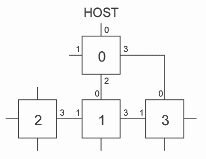
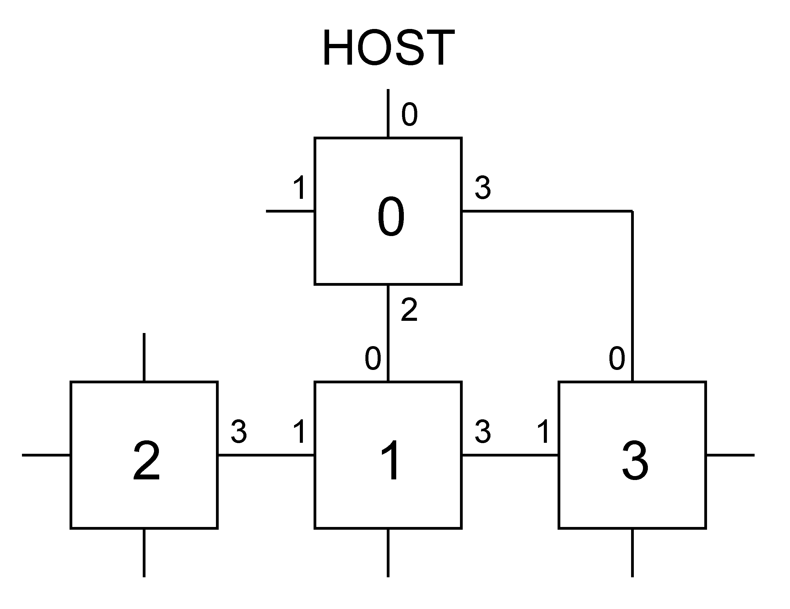
Figure 1 below shows a simple network which will be used as an example to show how RSPY operates.
To start with, the host boots node 0 with the leafworm and then the mapworm. Node 0 then explores its links. Link 1 is unconnected so is ignored. Link 2 is connected to another transputer, which is booted and becomes node 1. Node 0 enters relay mode while node 1 explores and boots node 2 on link 1. Node 2 has no daughters so returns details of its connections and type to node 1; this data is returned to the host via node 0. The mapworm on node 2 terminates and node 1 boots the routeworm on top of it. Having done that branch, node 1 probes link 2. It finds nothing at the other end so probes link 3 and finds a valid transputer. This is booted and becomes node 3. Node 3 probes link 0 and receives a message from node 0 saying that it has already been booted. Node 3 checks the rest of its links and finds nothing. The sequence of returning results, terminating the mapworm and being booted with the routeworm then happens to nodes 3, 1 and 0 in sequence.
The host now has a map giving the network connectivity. It opens a connection to each node in numerical order and runs the part determination program on it. The results are collected at the host and displayed for the user.
One important point applying to all three worms is that they must be as small as possible. This is because they have no knowledge of the external memory available to each transputer and must therefore fit into the 2k of on-chip RAM which every transputer is guaranteed to have.
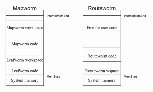
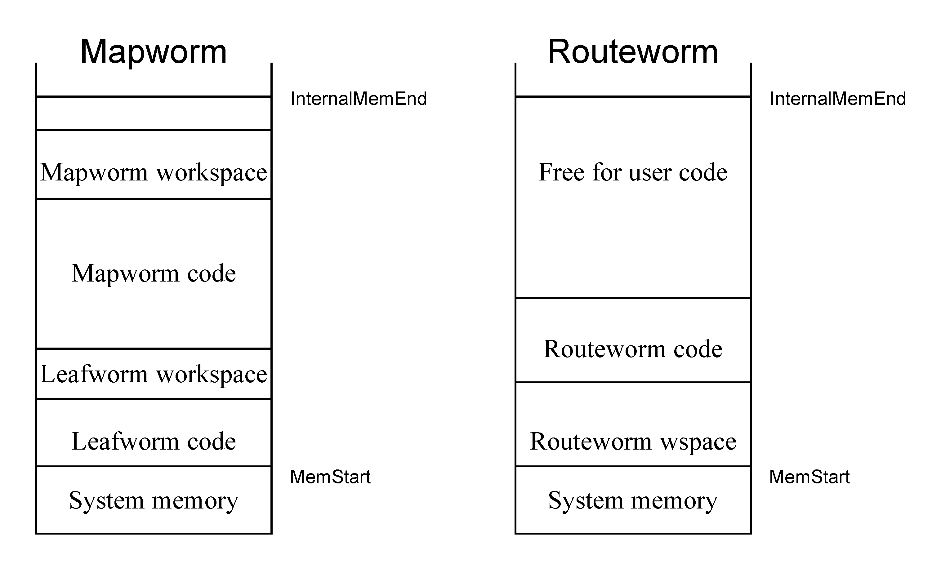
The worms are arranged in memory as follows. The leafworm is loaded at MemStart, followed by its workspace. The mapworm code and workspace follow. Four words are reserved after the mapworm workspace so the leafworm can pass in a pointer to the link connecting it to the parent; the leafworm wptr and iptr are also stored so the leafworm can resume execution after the mapworm has terminated.
The arrangement for the routeworm is slightly different. As the leafworm is no longer needed, the workspace of the routeworm is placed just above MemStart. Code and workspace used by the program loaded by the routeworm follows after the routeworm code.
Figure 2 shows the memory map for the mapworm and routeworm.
As the memory allocation is so critical, a small program called checkwsize has been written which examines the leaf- and map-worms and returns an error status of 1 if the code will not fit into 2K. It can thus be used in a makefile as part of the RSPY build.
As the first program to be booted upon a transputer must be less than 256 bytes long, the leafworm has to be written in assembly language. Its first task is to initialise the processor: this involves clearing the error flag and setting the process queue, link, event and timer queue registers to NotProcess.p
After this has been completed, the leafworm enters a loop in which code is loaded from the parent and then executed. To load code, the parent sends the address where the code is to go and its size as INT16s followed by the code as a series of bytes. It then sends the iptr and wptr of the loaded code. To run the code, the leafworm stores its iptr and wptr then adjusts the iptr and wptr to point at the loaded code.
The goal of the mapworm is to form two data structures :
[NumLinks][connections.fields]BYTE connections and
[node.data.fields]BYTE node.data.
The former describes what is connected to each link. There are three fields for each link: the type of device at the other end, its id number of that remote device and its link number. The type can be one of the following:
| type.probe | link not yet probed |
| type.16bit | 16bit unbooted device |
| type.32bit | 32bit unbooted device |
| type.already.booted | booted device further down the tree |
| type.unconnected | |
| type.C004 | |
| type.host | |
| type.done.16 | 16bit booted device |
| type.done.32 | 32bit booted device |
| type.error | |
node.data contains details of the node that the mapworm is running on. There are two fields: the type (which is as in the table above) and the number of the link connecting the device to its parent.
Each node in the network is given an id number. This is an INT16, to allow networks with up to 64000 nodes to be explored. The numbering system used in [1] is also used here: nodes are numbered in the order that they are booted.
On starting, the mapworm inputs data from its parent which allows it to fill in connections for the bootlink. Then, it constructs the node.data. After that it examines each link in turn, booting daughters and entering relay mode if necessary. Finally, it sends the two data structures outlined above back down its bootlink to the parent and returns control to the leafworm.
While one link is being examined, the other links must be listened to so the loop-back problem outlined in section 2 above can be solved. This listening should go on even during the initial probe of a link as the link may be connected to another link on the same device.
The initial probe is handled by the procedure look.down.link. If the link is either connected to another transputer or disconnected, then we could send a peek/poke sequence using OutputOrFail.t as outlined in [1] However, if there is a C004 at the other end, it will interpret the peek and poke commands as C004 connect commands. This could lead to the network being altered. To prevent this, a special sequence of bytes called the type bootstrap is sent down the link.
This is just a short assembly language program, carefully coded to avoid including C004 commands, which initialises the transputer and sends back a byte indicating whether it is a 32 or 16 bit device. At the end of the bootstrap is a reset sequence which returns the transputer to its previous, unbooted state.
After the reset code comes a C004 enquiry command. As the transputer has resetted. it will not try and execute this part of the sequence. A C004, however, will send back a byte, indicating to which link the link that we inquired about is connected to.
The outcome of all this is that whatever is at the other end of the link (apart from fresh air), it will send back a byte from which we can identify the device.
The assembly code part of the sequence multiplies 0x3F by the number of bytes per word and returns the result to the parent. Thus a 16 bit transputer will return 0x7E and a 32 bit tx 0xFC. The reply of the C004 to the enquiry will be a C004 link number. We are not concerned about the actual value; all we need to know is that it will be in the range 0x00-1F or 0x80-9F. For the special case of a transputer that has already been booted, the program controlling that transputer will return the byte 0xBD on receipt of a type bootstrap.
Below is a summary of what can be returned. look.down.link analyses the received byte and returns the type value shown in column 3.
| Outcome | Byte received | Returned type |
| C004 | 00-1F / 80-9F | type.C004 |
| 16 bit transputer | 7E | type.16bit |
| 32 bit transputer | FC | type.32bit |
| already booted transputer | BD | type.already.booted |
| timeout | nothing | type.unconnected |
On returning from the procedure, the mapworm updates connections. If the type is an unbooted device, it is booted and relay mode is entered. If the type shows that the device at the other end of the link has already been booted, the connections field for that link is exchanged with the field of the corresponding link.
C004s are treated as devices like transputers, and have id numbers assigned to them. However, as they cannot actually run code, the transputer that is connected to the control link of a C004 has to send back details to the host. So if the type was type.C004, the mapworm sends back to its parent the id that the C004 would have, the id number of the node, and the link number connecting the two.
In relay mode, data and code is transferred to and from the host and a daughter node. A transfer is initiated by the daughter sending a parent a byte which describes its request. This request is then passed on to the parent of the current node, which continues until the request reaches the host. The controller then sends or receives the data or code as required.
When a daughter node has finished, it sends back its connectivity and node data to the parent with a special request. This tells the parent that the daughter has terminated and should be loaded with the routeworm.
The routeworm is always in one of three states: processing commands at the present node, routing data to another node or waiting for code running on the present node to terminate.
The controller corresponds with the routeworms in the network by sending
packets of format
INT16::[]BYTE. The first byte of the array should be one of the commands listed
below
| Command | Action |
| R.open | Open connection to a daughter node |
| R.update | Load code into memory |
| R.run | Run code stored in memory |
| R.which | Report node id |
When a connection is opened to a daughter node, only open and close commands are recognised. Anything else is passed to the daughter; packets received from the daughter are similarly passed to the parent. The open and close commands are nested, so a node n steps away from the node currently being talked to will have received n open commands.
To avoid confusion with routeworm commands, packets sent to a program running on top of the routeworm at a node should have the command byte of the packet set to R.data.
A similar iptr/wptr storage mechanism is used to that of the leafworm, allowing the loaded program to be a normal occam procedure of form
PROC user.program (INT parent, my.id)
where parent is the bootlink number and my.id the node id number.
The controller is composed of six source code files:
| File | Task |
| rspy.c | Main module and user interface |
| bootnet.c | Starts the worm system on the first node in the system |
| dispatch.c | Controls the routeworms |
| loadrsc.c | Loads the worm RSCs from disk |
| txiface.c | Interface to the linkops system |
| utils.c | Various useful utilities |
The transputer version has no txiface.c; the other files are all different, especially bootnet.c which has to include part of the functionality of the mapworm in a non-hosted version.
One important data structure used by the controller modules is the map:
typedef struct {
BYTE remotelinkno; struct mapNode *connection; } Link; typedef struct mapNode { INT16 nodeid; BYTE type; BYTE bootlink; Link link[NumLinks]; } Map; |
Each node in the network has a mapNode entry. This is formed and linked to other entries by bootnet.c, from connections and node.datas sent back to the host by the mapworm. As the topology of the network is unknown, map nodes cannot be alloc’d as results are sent in by the mapworm: the connections may refer to nodes not yet declared in the map. Instead, an array of map nodes is declared and a pointer to the first node passed to the various routines; in this way, each node can be randomly accessed while allowing a linked list method to be used.
Below is a list of the functions intended to be called from the main RSPY module. Section 4 includes a short piece of code showing how they can be used.
extern int BootNetwork(Map *map, char *resource
This routine explores the network using the leafworm and mapworm, then boots the routeworm onto every node. *map is a pointer to the first node in the map; resource is the name of the transputer resource to be accessed. If it is NULL, the default resource is used. The function returns 0 if it is unable to explore the network properly.
extern void DisplayMap(Map *map)
This will display the map as produced by BootNetwork on screen using an ispy type format. Normally, the routeworm would be used to run a program on each node that determines its part and rate, and this information would be combined with the map to form the full ispy display.
extern int IsTransputerType(BYTE type)
Returns 1 if the type code is that for a valid transputer
extern char * TypeToString(BYTE type, char *typeString)
Converts a type code to a printable string
extern int InitDispatcher(char *ursc16, char *ursc32)
Here, the parameters are the filenames (respectively for the 16bit and 32bit version) of the RSCs that are to be run on each node using the routeworm. The routine will read in the files and initialise the dispatcher, the code which controls the routeworms. 1 is returned if successful.
extern int StartRSCOnNode(Map *map, int node)
After the dispatcher has been started, use this routine to start the user RSC on a given node. The dispatcher will work out the path to the node, open a connection and then send the code, iptr and wptr. If the correct node has been reached and the code starts ok, 1 is returned.
extern void SendRouterPacket(char *buffer, int len)
This routine forms a routeworm packet from a data buffer of size len and sends it to the node that is currently connected to the dispatcher.
extern void GetRouterPacket(char *buffer, int *len)
This routine receives a routeworm packet of arbitrary length; the data, length len, is retuned in the buffer.
extern void StopDispatcher(void)
After all the desired user programs have been run on nodes, call this routine to close all connections to the network and shut down the dispatcher.
If RSPY is being used as a ispy replacement, the user RSC that is loaded onto every node is part.occ. This simply determines the part code (T212, T400, T800 etc) of the node and the rate in MHz that it is running at and returns this data as bytes 1 and 2 of the data section of a router packet.
The RSPY system was designed to be as general as possible. After the initial network exploration, it is possible to run a small occam program on any transputer in the network.
To do this, two pieces of code are needed: the RSC that is to be run on the node and a controller that will process results sent back by the user program.
The user program should be similar to the example in Figure 3:
parent is the number of the link connecting the node via the routeworm to the host; my.id is the node id number as used in the map.
Communication with the host should be done with router packets. These have the format INT16::[]BYTE. If data is being sent from the host to the node, the first byte of the array should be the special value R.data to avoid the routeworm confusing the packet with a router command. Packets sent in the reverse direction do not have this restriction.
The code should be compiled to form a RSC for 16- and 32-bit targets. The -zv and -zw options should be used to allow PLACEing of arrays of channels. To save space, all debugging and usage checking should be turned off.
As an example, the code sequence in Figure 4 shows how the RSPY system can be used.
|
Note that networkSize is a global set in BootNetwork that indicates the number of nodes (C004s and working transputers) in the network.
[1] Exploring Multiple Transputer Arrays, INMOS Technical note 24.