|
|
| Connecting 100MBaud T9000 transputer links _____________________________________________________________________ |
| INMOS April 1991 |
Digital design engineers are accustomed to signals that behave as ones and zeros. We know that in our chip design and board design, we have to be more careful than we used to be about dissipation and ground inductance. As speeds on chip get faster these become even more important.
We also know that as speeds get faster, the interconnect delays dominate the delays on chip, and that it is ten times faster to do things on one chip than between two adjacent chips. When the chips are next to each other, we just put up with the delay; when they are on the same PCB, we add a bit more delay. When they are in different boxes...?
Communications engineers are accustomed to disappearing signals. They design modems that send 19200 bits per second down a telephone wire that was designed 90 years ago to carry 3.4kHz of voice. Their signals go thousands of kilometres. They are used to multiplexing lots of slow signals down a single fast channel. They use repeaters, powered by the signal wires.
Fortunately, as digital designers, we don’t have to use all the communications tricks yet. But like the dissipation and ground inductance problems, we do need to recognize that sending 100Mbit/s to several Gbit/s down a cable much longer than a metre brings implications that are more analog than digital.
Actually, it is possible to overestimate the problems of these signal speeds. Engineers, who have been designing with ECL, even fifteen years ago, had to deal with some of the problems at least on printed circuit boards (PCBs), backplanes, and short cables. One of the best books on the subject is the Motorola ’MECL System Design Handbook’ [1] by William R Blood, Jr., which explains about transmission lines on PCBs and cable. He shows waveforms of a 50MHz signal at the end of 50ft (15m) of twisted pair, and of a 350MHz signal at the end of 10ft (3m) of twisted pair, both with respectable signals.
This technical note first discusses the signal properties of transputer links. PCB and cable connections are then described, and are followed by a section on error rates: errors are much less frequent on transputer links than is normal in communications. A longer section introduces some of the characteristics of optical connections including optical fibre, which should be suitable for link connections up to 500m, but which needs an interface chip to convert between the link and the fibre. A pointer is given towards possible standards for link connections. An appendix describes a proposed connector that would assist standardization of transputer link connections, and a further appendix shows waveforms of signals transmitted through cable and fibre.
Considerable design work has gone into making the T9000 link signals [4] well behaved for such fast signals. The design of the bit-level protocol, as well as of the electrical characteristics, contributes to make the link signals unusually easy to use for 100MBaud signals.
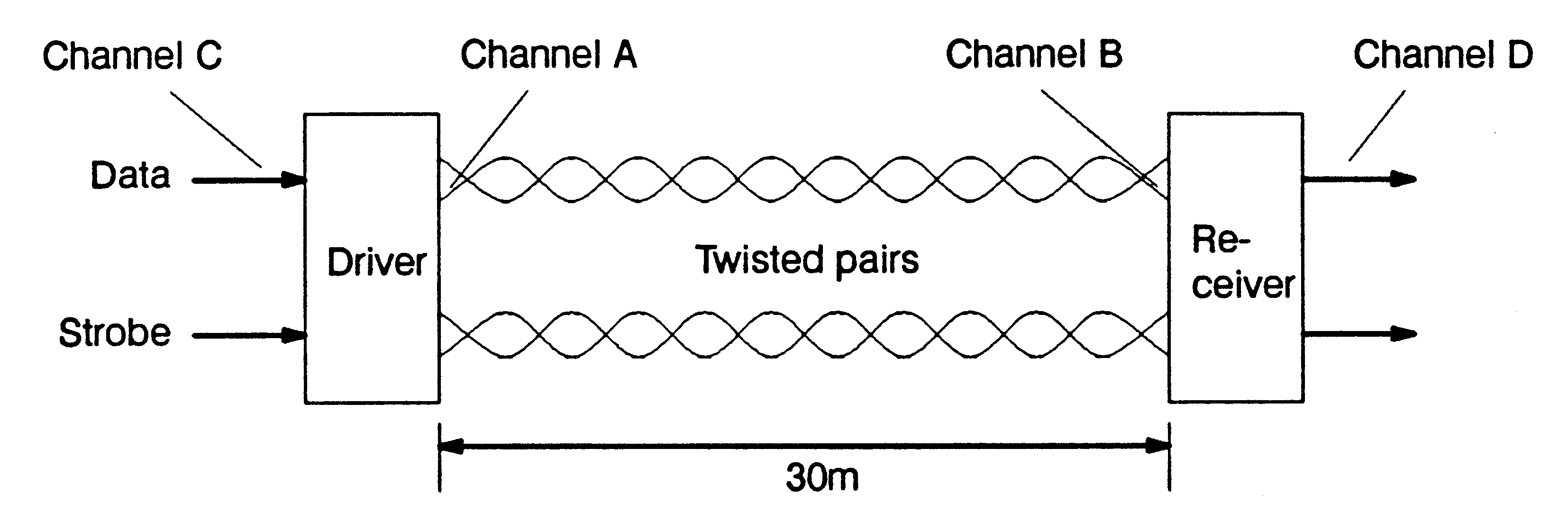
The T9000 link signal is carried by a pair of wires in each direction. The D signal carries data bits, a control bit to distinguish between data and control tokens, and a parity bit which checks both the data bits and the control bits. The S signal is a strobe, which changes level every bit time that the D signal does not change. This bit-level protocol guarantees that there is always a transition on either D or S every bit time, but that only one of the two signal wires will have an edge in each bit time. Effectively this provides a Gray code between the D and S signals.
One result of the DS Gray coding is that the received data is decoded from the sequence of D and S rather than on any absolute time. This effectively makes the link receivers ’autobaud’, receiving data at whatever speed it is sent (so long as the receiver logic is fast enough).
The Gray coding makes it much easier to design logic that is fast enough, because the timing resolution required is a whole bit time. Alternative coding would require a clock edge in the centre of a data bit, and hence require timing resolution of half a bit time. The more relaxed timing resolution needed by the DS links gives major benefits in terms of the performance that can be achieved in practical systems.
A further advantage of the coding, with only D or S changing at a time, is that the signal can be received without a Phase-Locked-Loop (PLL) - the clock is just the Exclusive-OR of the D and S signals. For the C104 routing switch, avoiding the need for 32 PLLs is very valuable, and it is possible that a 32 way routing switch would not be possible had the PLLs been required.
Electrical aspects of the design include controlled output impedance of approximately 100Ohm not only when high or low but also during transitions. Obviously there is a tolerance on the impedance, and it may not be identical for high and low, but even with these tolerances it has been designed to minimize the effect of any mismatch on the signal.
The link outputs have also been designed to give controlled rise and fall times. The full electrical characteristics will not be known until the devices are fully characterized, but a reasonable estimate of the transition times is 3ns fastest transition and 6ns slowest transition.
The DS coding gives as much tolerance as possible for skew between the D and S signals, and the outputs and inputs have been designed to have minimal skew at the TTL threshold of 1.5V.
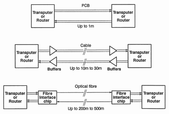
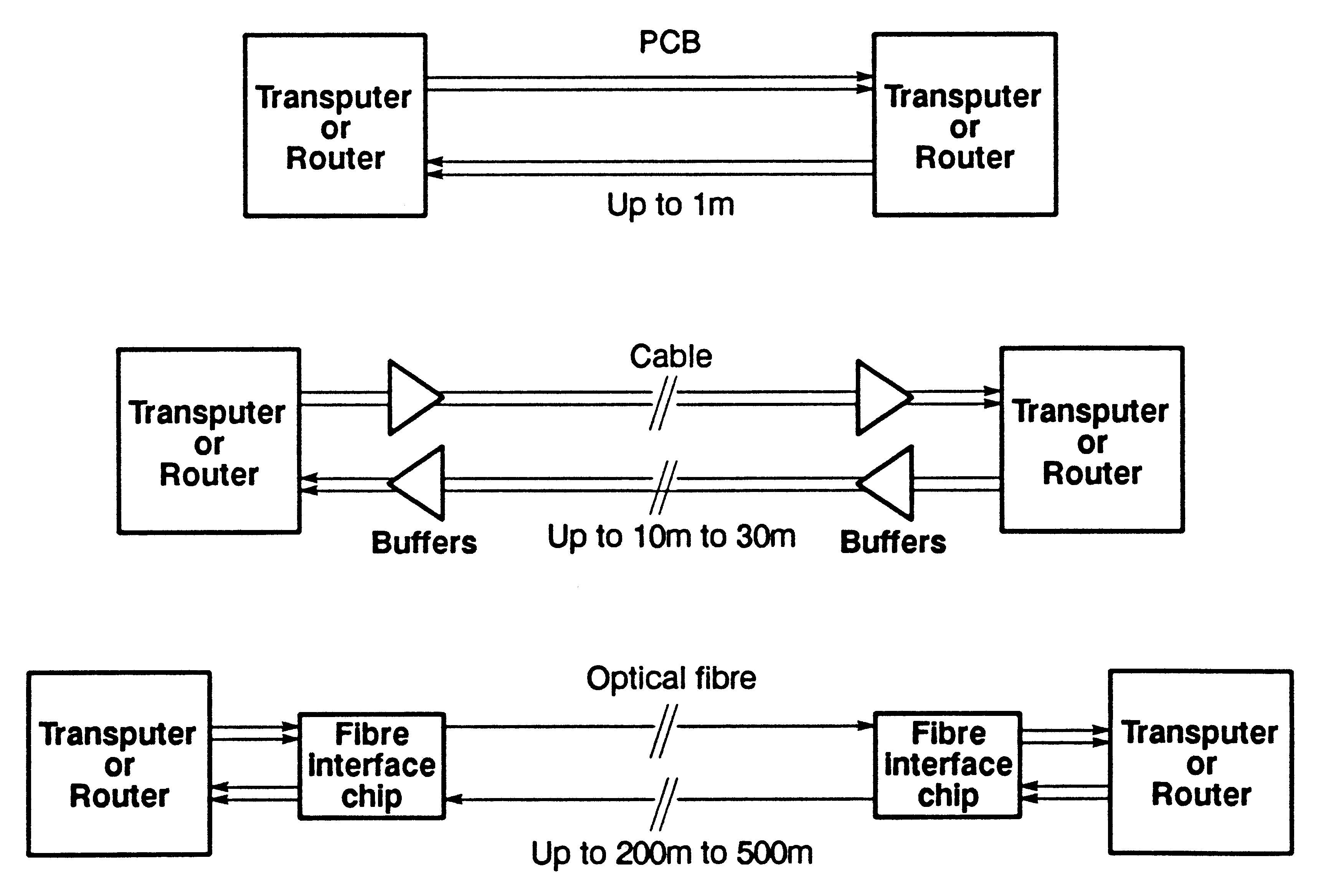
These characteristics of the DS link signals make them ideal for connections on PCBs, and for DC coupled connections on short lengths of cable, up to 10 to 30m. Later sections will describe such connections, as well as much longer connections up to 500m.
The following discussion assumes the use of multilayer PCBs with power and ground planes; use of 100MBaud links on double-sided boards without ground planes is not recommended.
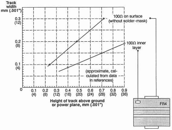
The 100Ohm transmission line impedance is fairly easy to achieve on the surface of a PCB. INMOS has built PCBs with long connections of 100Ohm impedance, and they carry link signals faithfully. The 100Ohm impedance requires a track width something between 0.1mm and 0.3mm, depending on the board thickness and where the power planes are located within the thickness. Figure 1 shows the approximate relationship between these parameters for standard FR4 PCB material with a dielectric constant of 4.7. (Figure 1 is derived from data given in Blood [1], from SONY [2], and from Coombs [3].)
Note that when a PCB track is buried in the fibreglass/epoxy laminate, its impedance is reduced by about 20% compared with a surface track. This probably requires the inner layer tracks to be narrower than surface tracks, to minimise differences in impedance. It is not possible, within the normal 1.6mm board thickness, to have 100Ohm tracks sandwiched between power or ground planes.
If the transmission line impedance can be maintained, PCB connections of links will be good for several metres. If the impedance can be maintained approximately, but with a wider tolerance than specified for T800 style (OverSampled) links, it is probably best to limit the connections to two or three propagation delays, or 600 to 900mm with standard FR4 PCB material. If the Impedance goes outside the range of 80Ohm to 125Ohm, it is probably best to limit the connection to four or five propagation delays, about 360 to 450mm.
Short discontinuities in the impedance are permissible, such as in connectors and for short sections of tracks; such discontinuities are probably best kept less than 50mm.
Similarly, if it is necessary to use some PCB tracks of higher impedance than 100Ohm, and some lower than 100Ohm, it is best if they can be alternated in short sections, rather than having a 400mm length of 125Ohm track and then a 400mm length of 80Ohm track.
The controlled transition times of the D-S links minimise crosstalk compared with the sub-nanosecond fall times of some of the fast families of ’TTL’, but care still needs to be taken over crosstalk. At the time of writing, tests and simulations were not complete, but suggested that backwards crosstalk increases up to a length of parallel tracks of 20 to 25cm, and does not increase for longer parallel tracks. Track separation of 0.15mm over this length appears to give 1 volt of crosstalk, which is above the noise margin. Simulations of track separation of 1.25mm over a length of 20cm give crosstalk figures of less than 100mV.
The references [1], [2], and [3] do not give a great deal of information about PCB crosstalk, and the results indicated above suggest that further work is required. In the meantime, it must be good practice to avoid long parallel runs, to space the tracks out as far as possible, and where possible to put 0V tracks between link tracks.
The D and S pair of signals should be approximately the same length, but a difference in length of 50mm would only introduce a skew of 250ps, which should be totally acceptable.
This section looks at existing cable interfaces, comparing them with transputer links, and then discusses the loss and noise that occur in a cable, and what can be done to overcome their effects.
Ethernet connections are now inexpensive, with a component cost well under $50 and an end-user cost around $150. Transputer links are even less expensive with a $20 T400 having two links each capable of 20Mbit/s full duplex, a total bandwidth four times Ethernet at a cost of $10 per port including the processor and on-chip RAM; if these are excluded, the T400 link cost is nearer $2 per link.
Token Ring goes a little faster than Ethernet, but to go substantially faster the next standard is FDDI at 125MBaud (of which 100Mbit/s are useful data). FDDI is expensive, not only in its protocol, but even in its components, and just the transceiver is not expected to reach $100 in volume for some time.
Links on the T9000 transputer will run at 100MBaud, full duplex. Whatever the volume price of the transputer, the cost per link (with the processor and memory thrown in) is likely to be considerably less than either the chipset or the transceiver for FDDI. The C104 routing switch, with 32 ports, probably for less than the cost of a transputer, will give a cost per port well under $10 - at least an order of magnitude less than the FDDI component cost.
Ethernet, Token Ring, and FDDI are all local area networks, with many ports in a network and long distances between ports. Transputer links are point-to-point, and are generally expected to be comparatively short connections. In this respect they are more like the recent parallel interfaces such as SCSI2, IPI and HPPI.
HPPI as an example has a maximum length of 25m, and runs at 800Mbit/s in one direction down a cable with 50 twisted pairs. The same speed in both directions requires two cables, and the speed can be doubled by using two cables in each direction.
FibreChannel is a fibre connection with similar data rates to HPPI, using laser diodes. This will allow much longer connections than HPPI, at drastically lower cable costs, but possibly with a high cost per port.
Copper wire has a finite resistance: 28AWG wire is one of the smallest cross sections in widespread use and has a resistance of 0.23Ohm/m, 1Ohm in 4.3m. If the characteristic impedance of the cable is 100Ohm, a resistance of 10 ohms is not going to affect the signal very much, so this cable should certainly be usable at 43m. The problem is that at high frequencies, the signal does not flow evenly throughout the conductor but concentrates at the outside of the conductor - the skin effect. So as higher the frequency of a signal is, as higher is the resistance of the cable. Some of the energy does not flow in the conductor at all, but in the insulation and, if it can, in adjacent conductors causing crosstalk as well as loss. Some of the energy is sent into the atmosphere to interfere with radios and other users of the airwaves.
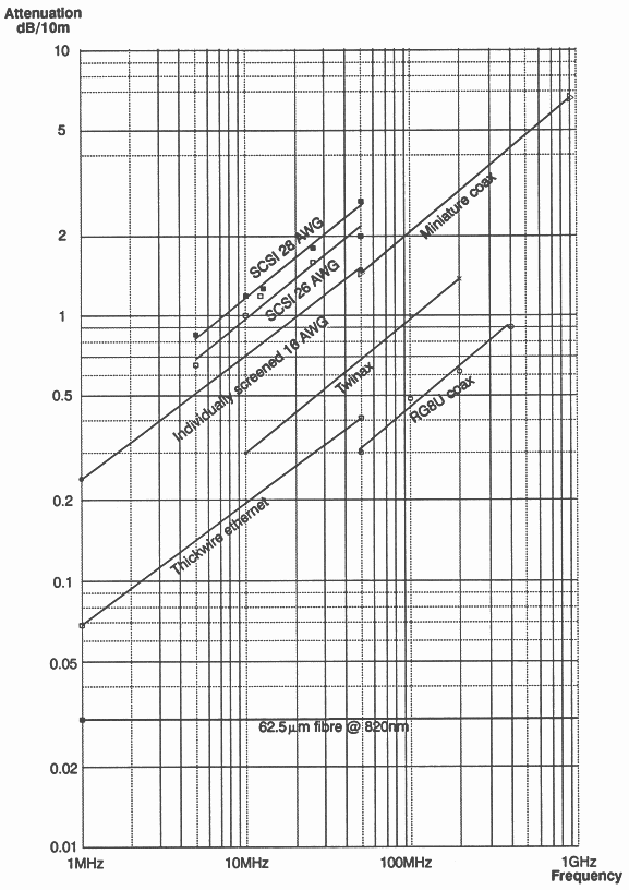
The sum of these losses of energy which depend on frequency is measured in dB (deciBels) per unit length. Figure 2 plots these losses for a number of cables - some inexpensive, some extremely expensive. The detail is not important but note that for all of them, the loss increases with frequency, and that most of the graphs are straight lines with the same gradient.
The increase of loss with frequency means that the further you want to connect at a given frequency, the less ’loss’ (and probably more expensive) cable you will need. Above some length of connection, the losses have to be compensated for somehow - as in Telecommunications - and more tricks have to be used, increasing the cost of the circuitry at the ends of the cable, and possibly adding repeaters in the cable. At some stage, it will become worth while to use optical fibre, an example of which is shown in figure 2.
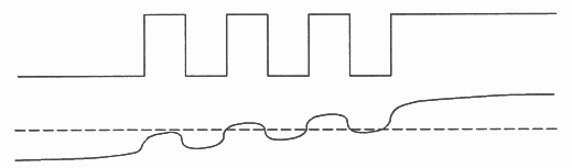
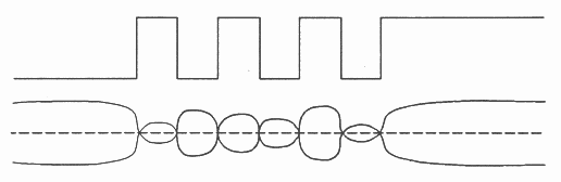
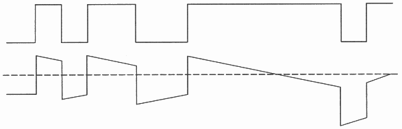
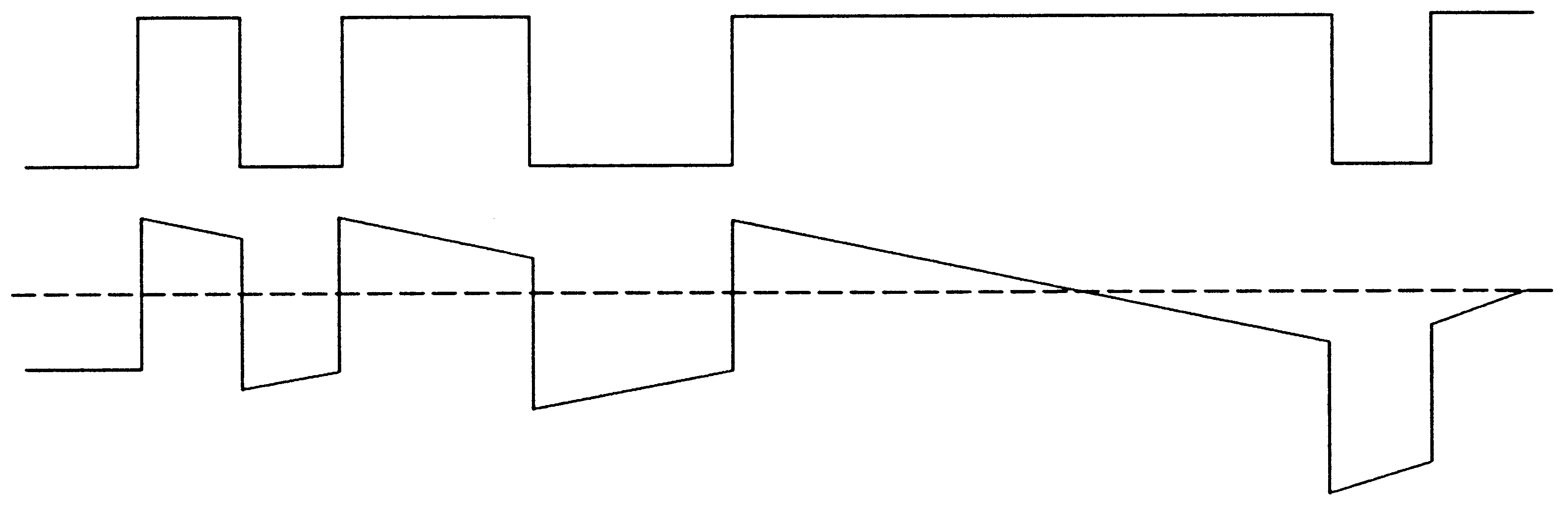
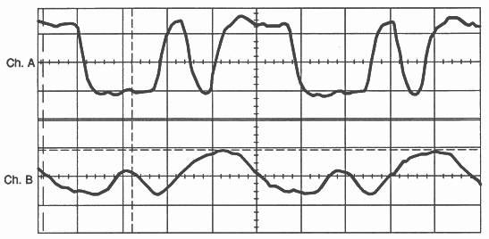
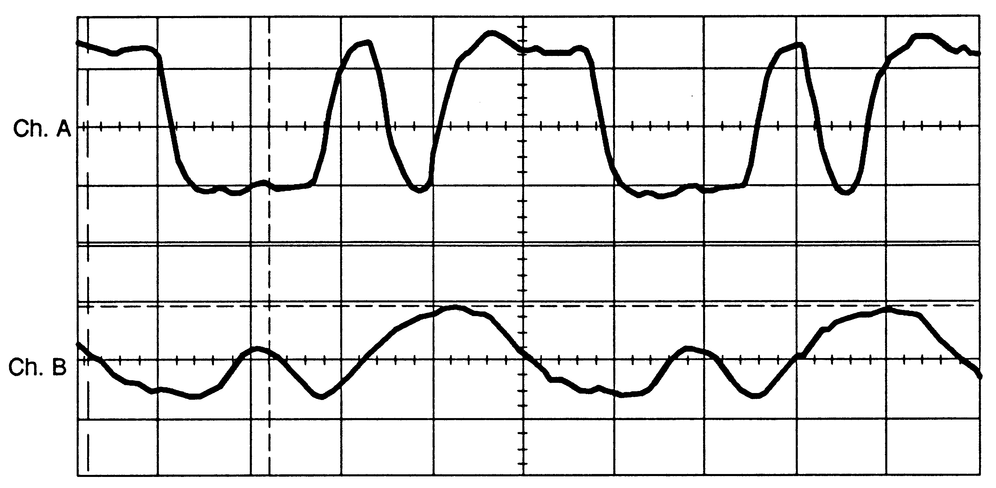
The increased loss at high frequency can be overcome by using a cable short enough that the loss is minimal. For some of the cables at 100MHz, this could mean less than a metre. The effect of using a longer cable is distortion of the signal. Figure 3 shows the sort of thing that happens to an NRZ (Non Return to Zero) signal which has suffered a 10dB loss1 at the frequency of the square wave. The dotted line represents the DC threshold of the signal, which suggests that the signal will not be received correctly, even if there is no noise.
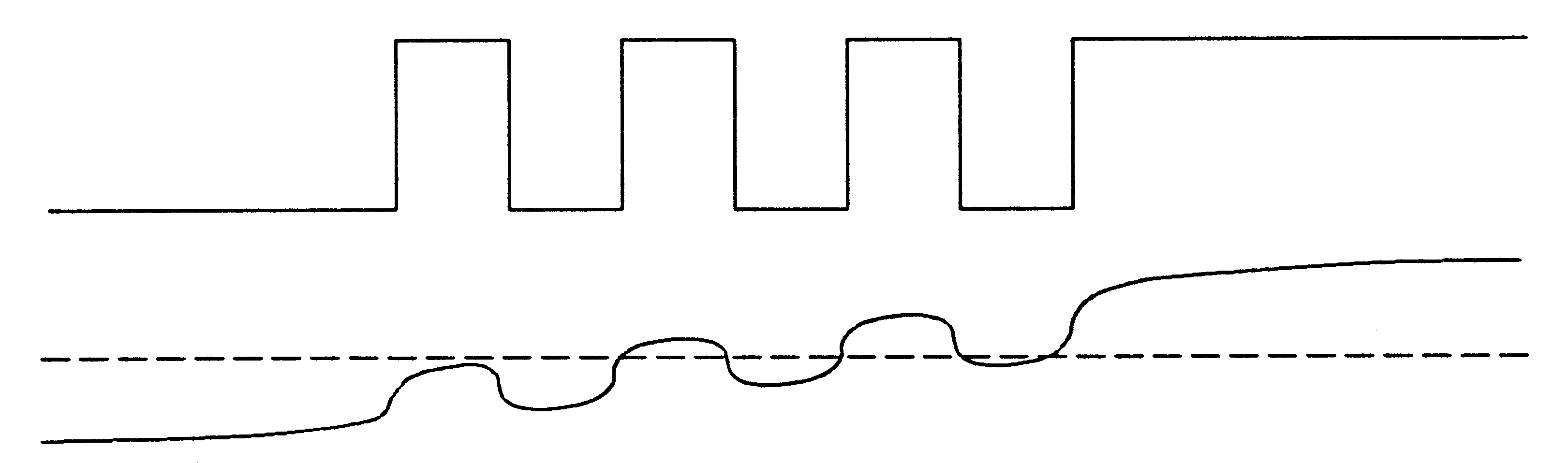
Figure 4 shows a similar effect to figure 3, but the received high frequency voltage is now about 0.6 times the transmitted voltage, representing a loss at this frequency of around 4.5dB. At 100Mbit/s, the ’sine wave’ part of figure 4 is 50MHz, and the 28AWG IPI/SCSI2 cable2 shown in figure 2 has a loss of 2.8dB for 10m at 50MHz, so if we are lucky this cable might just work not at 43m but at (4.5/2.8) x 10m or 16m – as long as there is no noise, and the receiver has sufficient gain and is tolerant of small errors in timing.
But in the real world, there is noise, and it will not work.
For a cable several metres long between two boxes, there is crosstalk and there can be no guarantee that there is no difference between the boxes’ ground or logic 0V levels. Any difference will be seen as noise.
A good way to remove both cause and effect of the difference in grounds between the two boxes is to send differential signals. These are shown in figure 5. Any difference in ground voltage will be seen as common mode by a receiving differential buffer.
A popular use of differential signals is RS422, whose receivers have a common mode tolerance of 7V beyond the maximum signal levels. The RS422 components are limited to 10MBaud or 20MBaud, but have been used by many transputer users to connect T800 style transputer links between boxes and have proved to be extremely reliable when so used.
ECL buffers are much faster than the RS422 components. Blood shows ’scope traces of a 350MHz signal after a receiver at the end of 10ft of twisted pair. The ECL common mode tolerance is much less than RS422, from +1V to -1.8V or -2.5V depending on the device used.
A family of devices from AT&T (41 series of High Performance Line Drivers, Receivers, Transceivers, pin compatible with 26LS31 and 32) offers speed approaching that of ECL together with common mode tolerance close to that of RS422. The transmitters have TTL inputs and pseudo-ECL outputs, and the receivers convert the pseudo-ECL back to TTL. One range of devices runs up to 100MHz (200MBaud), another to 200MHz (400MBaud). Common mode tolerance is from -1.2Vto +7.2V, with the 1V signal approximately in the middle of this range.
DC coupling with ECL or with the AT&T circuits, over the 16m suggested in the last section for 100MBaud signals, ought to work3.
Larger common mode voltages between two boxes can be overcome by using AC coupling or some other form of isolation. At microwave frequencies (perhaps above 400MHz) it is difficult to buy amplifiers that are not AC coupled.
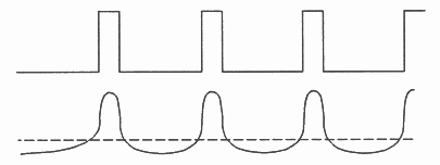
In the last section, we overcame some problems by using balanced, differential signals. A different sort of balance is important in AC coupling. Figure 6 shows a signal which has a mark-to-space ratio of 4:1. On the receive side of the AC coupling, the threshold is set by averaging the received voltage. As a result, the threshold is heavily offset, reducing the noise margin and changing timings.
In order to provide DC balance, so that the threshold is in the middle of the signal, the data is coded in some way, usually by adding redundant bits to achieve the desired signal characteristics. One of the most popular forms of DC balanced coding is Manchester Code, which provides DC balance over every bit period. An alternative to coding is to modulate a carrier, in amplitude, in frequency, in phase, or in combinations of these, with different data values being represented by different amplitudes, frequencies or phases; the carrier is a sine wave which is inherently DC balanced.
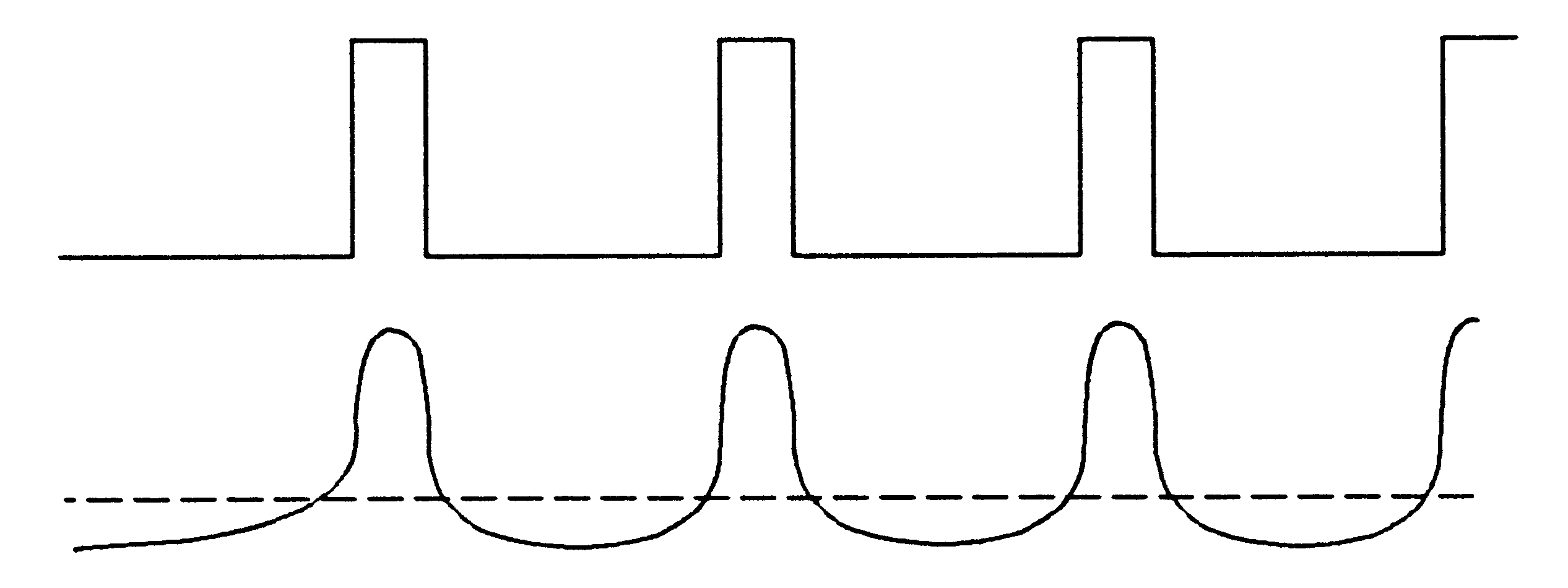
Even when there is no DC component, a long period without a transition can cause the signal to disappear. Codes therefore have a maximum run length to limit this time between transitions; they also have a minimum run length, to ensure that two adjacent edges do not cancel each other out and appear as no edge. Figure 7 shows the effect of a long run length: the signal droops, reducing the margin between the signal and the threshold, until it eventually crosses over the threshold.
Some of the codes which are currently popular are not in fact completely DC balanced, but for most data patterns have minimal DC component. Such codes Include the 2:7 Run Length Limited code used on disks, and the TAXI/FDDI code which is never worse than 40%/60% balanced. (The code used by FibreChannel has the same efficiency as the FDDI code, but is completely DC balanced.) A technique used on ISDN and on SONET is to scramble the data so that it is approximately balanced and very rarely has long run lengths; the scrambling has the advantage that no extra bits are added to the data.
An extreme form of AC coupling is to differentiate the signal, which provides inherent DC balance. The precompensation circuit used in twisted pair FDDI effectively produces the sum of the signal itself, plus a differentiated version of the signal. In magnetic recording, such differentiation occurs naturally, but it brings its own problems; any noise such as crosstalk is coupled through the differentiator, and any AC imbalance in common-mode coupling is translated into extra noise.
AC coupling can either be provided by transformers or capacitors. Transformers provide excellent common mode isolation and are readily available at low cost up to a few hundred MHz (Mini-Circuits T1-1 0.15MHz to 400MHz, $3.25 in low volume). Capacitors do not provide good common mode isolation, but can be used for frequencies up to many GHz. Low cost amplifiers are also available which must be AC coupled, with 7.5dB gain at 1.5GHz.
The constraints on run length and on the DC balance effectively reduce the bandwidth that needs to be received. If the highest frequency needed is 50MHz, and the lowest is 10MHz, the 28AWG cable referred to above loses 2.8dB in 10m at 50MHz and 1.2dB at 10MHz. So we only have to cope with a difference of 1.6dB per 10m between the frequencies. Instead of the 16m limit given above for the differential DC coupled case giving 4.5dB, we can AC couple, use more gain, and should be able to reach (4.5/1.6) x 10m or 28m4.
An extreme case of bandwidth limitation is Cable TV, which pumps a number of N channels long distances down coax. They use a carrier of 900MHz, but only have a bandwidth for each channel of 6-8MHz: although the attenuation of the 900MHz is very high, the difference in attenuation between 897 and 903MHz is much smaller. The required frequencies are picked out by a tuned amplifier.
Even with a very wide bandwidth, it is possible to use tuning (tweaking?) to compensate for the frequency characteristics of the cable. As with ’scope probes, it is easier to do if the tuning is built into the cable (otherwise it has to cope with a wide range of different cable lengths). As with ’scope probes, this can be expensive and liable to misuse.
The form of serial communications that most engineers are familiar with are LANs and very long distance (tele-)communications. For these long distance connections, error rates tend to be around 10−9 or less, which at 100MBaud is an error per link every five seconds (counting a link as bidirectional). Telecomms and LANs also need to cope with buffer overflow.
For these high error rates, it is absolutely necessary to have CRCs for error detection, and to have re-try mechanisms for corrupted or lost data - whether lost as a result of data errors or buffer overflow.
Another reason for needing CRCs is that most of the efficient communication codes, such as FDDI and FibreChannel, allow an erroneous single bit in the received data stream to be decoded as a valid (but incorrect) data symbol; both the FDDI and FibreChannel codes limit such decoded errors to less than a byte of data, but such error multiplication necessitates the use of checksums such as CRC.
The situation with transputer links is rather different: the flow control of the DS links means that buffer overflow can not occur; and specified error rates on PCBs are substantially better than 10−20, which is a failure per link every 50 000 years. At such error rates, it is quite reasonable to consider a system as reliable, and to crash the system if an error occurs. Alternatively, it is possible to add software to detect the rare event and to take some form of recovery action. In practice, at these error rates, hardware errors are much more likely to be caused by lightening strikes or by mechanical damage than by electrical signal failure.
The parity check on the DS links is such that a single bit error, either in control or data, is detected. As long as the errors are infrequent (one every several thousand years), this is entirely adequate. If a user is concerned about the possibility of an error not being detected, software can be added to the processes at the end of the link to perform more rigorous data checks and to recover from data or control errors.
These software checks can be performed even if the suspected virtual channel goes through a routing switch. The suspected link can be configured in the routing switch to go to a single transputer which is programmed to check the messages, effectively ignoring a possibly corrupted routing header. If several transputers are programmed to check the messages, the routing switch can be configured to route the messages to any of these transputers - but not to another routing switch or to a transputer that is unable to check the message.
The specifications stated in the transputer data sheets are designed to ensure the very good error rates that are expected between logic devices on a PCB. As a result, the permitted skew specification for the T4xx and T8xx transputers is a few nanoseconds. Some users have observed that links work with skews of several tens of nanoseconds; they do, but with such large skews the error rates are more like the 10−9 of the telecommunications and LANs. At INMOS, we have a network of transputer links, buffered with RS422 buffers, with connection lengths of close to 100m - way outside our specification or recommendations; in practice, the incidence of software failure on this network is substantially higher than the incidence of hardware errors due to links.
DS links will be specified, therefore, so that they give such infrequent errors that the hardware can be considered reliable, and that the probability of a single bit error is so low that the chance of an undetected double error is negligible. This does not preclude any user from adding checking software; nor does it preclude the use of more elaborate checking hardware when connecting links over longer distances such as with optical fibre interconnections.
Included in this section on optical interconnection are optical isolators which retain electrical connection, but offer large tolerance of common mode noise, and optical fibre, which comes into its own for connections much above 10m.
Optical isolators appear to offer the best of both worlds, in that they do not require the DC balance or run length limits that AC coupling needs, but yet offer almost infinite tolerance to common mode.
To make opto-isolators fast, however, most of the circuitry needs to be included that would be used in an optical fibre connection. As a fibre connection would cost less than the wire connection and go much further at a given speed, it may be preferable to use fibre. Whether this is the reason or not, I have been unable to find opto-isolators that are specified to run at 100Mbit/s or above.
The fibre shown on figure 2 is inexpensive but is much better in terms of its attenuation than the best copper cable. Single mode fibre is still better.
The problem is not in the attenuation in the cable, but in the losses (and consequent costs) in converting from electricity to light at one end and from light to electricity at the other end.
The light is produced by a LED or by a Laser Diode. An example LED outputs (infra-red at 1300nm wave length) 0.25mW of optical power when driven by 100mA of electrical power. Laser diodes are more efficient, one for example produces 5mW of optical power for 50mA of input current. The fastest LEDs have an optical risetime of about 2.5ns, and a 1.5dB cutoff at 100 or 150MHz (6dB around 800MHz). The 1300nm laser diodes have sub-nanosecond rise and fall times: one example has a very sharp cutoff at around 1.5GHz.
Components with wavelengths of 820 or 850nm are in many respects more suitable for 100MBaud transputer links. Components from HP and from a number of other companies include LEDs which output around 0.1mW (-10dBm) of optical power into the fibre with optical rise and fall times of 4ns, for a current of 60mA.
The receivers are PIN5 photodiodes, very often integrated into a hybrid with a pre-amp, and sometimes also with a power supply for the diode. The diodes are reverse biased, with a finite reverse (Dark) current. One example has a responsivity of about 0.5A/W. Assuming no attenuation in the fibre, 100mA into the LED becomes 0.25mW in the fibre which becomes 0.125mA in the PIN diode; this loss is far more than the electrical cable loss but fibre has the important advantage that, over short distances at least, there is much less variation of loss with frequency.
The received current needs to be amplified up to logic levels, and this amount of amplification, at these frequencies, is easier with AC coupling. So the requirements of bandwidth limiting, DC balance and run length limiting are present for optical fibre as much as for electrical wire. The FDDI transceivers and the HP 820nm 125MHz receiver module amplify up the current into a voltage - ECL levels from the FDDI transceivers, 10mV to 1V from the HP receiver.
The costs are radically dependent on the technology used (all figures are approximate and for large volumes):
| Wave- | Data rate | Light | Cost per | Availability |
| length | source | transceiver | ||
| (nm) | ||||
| 820 | 200kBaud | LED | less than $10 | now |
| 820 | 125MBaud | LED | $30 | now |
| 1300 | 125 to 350MBaud | LED | over $300 (FDDI) | now |
| $100 (FDDI) | long term goal | |||
| 1300 | 125MBaud to | Laser | $1000 to $10000 | now |
| 2.5GBaud | diode | |||
Notice that there is close to an order of magnitude cost difference between the 820nm and 1300nm wave lengths, and another order of magnitude between LEDs and lasers. The one exception to this is the 780nm laser diodes used for Compact Disks, which are discussed below.
Most of the work on fibre seems to have been to make it go long distances, often at very high speed; or to make it cheap, where speed and distance do not matter. FDDI seems to come in between these, in asking for 2km at 125Mbit/s, but they have chosen the more expensive 1300nm. In fact FDDI connections using lasers are now being developed to go further than the 2km, as Medium or Metropolitan Area Networks (MANs).
The 820nm components are limited in distance to about 500m at 100 or 125MBaud, which is more than adequate for transputer links.
The laser diodes that are used in compact disks have a wavelength of 780nm, which ties in well with the HP 820nm receivers for 100MBaud, and it is possible that the CD lasers could be used with faster receivers to provide 400Mbit/s. FibreChannel has specified one of the CD lasers as one of its options. These laser diodes are inexpensive because they are made in such large volumes for CDs, but the laser is not ideal for use by non-experts, and the laser diodes are not as reliable as LEDs.
At present, the cost, availability, and performance of the 820nm components appear to offer the preferred choice for transputer links.
The last few subsections have described a number of characteristics of the fibre connection which are not handled directly by the DS link:
The best way to do these various interfacing functions is with a link-to-fibre interface chip, designed for the purpose, as part of the transputer/link product family. We are working with users to firm up the specification of such a chip.
A number of users have asked that INMOS propose standards for interconnections between equipments, so that different manufacturers’ equipments can be connected by their transputer links. In some respects this provides a ’small area network’ of transputer or link based systems.
Our current proposal for cable connection is for DC coupling with the 41 series buffers mentioned earlier, with additional circuitry to improve the (already good) common-mode characteristics of these buffers. Earlier in this report, it was suggested that these cable connections should work well up to 16m and that tests have given good results at 30m, but for a standard it is probably advisable to round this down to 10m.
Our current proposal is that if isolation is required, it should be done with low cost optical fibre, rather than with transformer isolation and copper cable.
In drafting early versions of the proposed standard, we found that it was necessary to specify four different types of connector for different applications. There was no single connector which provided separate cables for each link, while meeting the other requirements. We therefore produced an outline specification of a single connector which would satisfy all the various requirements. INMOS can make no commitment about the resulting connector, either to our users or to potential manufacturers, and INMOS has no intention of selling the connectors except possibly as part of iq systems products. But several of the major worldwide connector manufacturers have expressed interest in developing and manufacturing a connector to the specification. An outline description of this proposed connector is included as an appendix.
The four connectors specified in the draft standard are 9-way D type, LEMO, SCSI2, and METRAL. Pinouts will be defined for these, for the MiniDIN, and for the proposed new connector.
Proposed standards for optical fibre connection are based on the fibre interface chip outlined above, with the low cost 820nm optical components, 62.5μm fibre (which is being installed into buildings for FDDI) and SC connectors (which appear to give a good combination of repeatability, density, and ease of use for the end-user).
The DS links have been optimised for short connections on printed circuit boards, for which they are ideal. The gray coding means that the receiver does not need a PLL, that there is a wide tolerance of skew, and that the receivers can ’autobaud’ without requiring a status register to set their speed. The comparatively slow edges - at least for 100MBaud - minimise crosstalk.
INMOS link specifications are designed to ensure that errors are sufficiently infrequent that connections can be treated as logic connections rather than as telecommunications or LAN connections. If users violate these specifications for links, systems will often work, but with error rates approaching the error rates seen by LANs. For these error rates, it is necessary to add software to handle the more frequent errors. Such software is not required when the specifications are met.
For PCB connections up to 20cm, the characteristic impedance of the PCB track does not matter. Up to between 60 and 90cm, the impedance should be kept within a reasonable tolerance - probably between 80Ohm and 125Ohm. Some care should be taken to avoid crosstalk. Beyond 90cm, PCB connections are possible, but the characteristic impedance should be more tightly controlled.
INMOS will be proposing link standards for long distance connections. Such standards will enable different manufacturers’ equipments to interconnect and, with cooperation on software, to inter-operate.
INMOS current proposals are for DC coupled cable connections up to 10m, possibly a little further. These will use fast buffers from AT&T which are similar to RS422 and have good common mode performance. For longer connections, up to 200 or 500m, or for electrical isolation, our current proposal is to use low cost optical fibre components, with a purpose designed interface chip.
These proposed standards to some extent remove from the user the need to understand fully the principles on which the standards are based. And at 100MBaud, over the distances suggested here, the problems are not especially severe. But the faster the signals and systems go, the more necessary it is to engineer them to avoid problems such as attenuation in the connection. I hope this technical note is a help in providing an understanding of these issues.
Many colleagues, especially in the transputer design and iq systems groups within INMOS, have provided information, work, or feedback on earlier drafts of this note. Many discussions have been held on the subject with David Boreham, Brian Parsons and Rob Simpson. Two students, John Carey and Mark Hill, both did a number of experiments to see how real life signals behave. Bob Krysiak has managed the design of the links, sponsored the work of these students and the experiments shown in Appendix B.
Howard Gurney and Darryl Cross in the iq systems group at INMOS have used the Swiftlogic software package to simulate the signal behaviour of PCB tracks, which confirmed previous experiments with manufactured PCBs. The package is available from Swiftlogic, of Cumbernauld, Scotland, and Santa Clara, CA.
Work on this subject has been supported under the ESPRIT ’Parallel Universal Message-passing Architecture’ (PUMA, P2701) project by the EEC, and more recently also under the ’General Purpose MIMD’ (P5404) project. Collaborators on these projects have made valuable contributions. Discussions with other users have also been very useful, particularly in finding out their experiences with existing links.
Also very helpful have been discussions with potential suppliers of components for both electrical and optical fibre connection.
[1] MECL System Design Handbook, William R Blood, Jr, Motorola.
INMOS’s copy is now old - dated 1983 - but it is an excellent book on
the subject of high frequency digital logic signals on PCBs and cables. It
also shows that the ECL system builders needed careful thermal design
some years ago.
[2] SONY data book of SPECL, 1990 edition.
This has a short application note with some comprehensive graphs of
transmission line impedance, capacitance, and delay.
[3] Printed Circuit Handbook, third edition, edited by Clyde F Coombs,
Jr, McGraw-Hill, New York, 1988 ISBN 0-07-012609-7.
This book covers all aspects of printed circuits.
[4] The T9000 Transputer Products Overview Manual, SGS-THOMSON INMOS, 1991, order code DBTRANSPST/1
There are many textbooks on communications but one of the most useful, which explains the concepts for a non-specialist and without excessive mathematics, is the Open University course ’T322: Digital Telecommunications’; this comprises a number of books, which are available separately or as a set from Open University Educational Enterprises in Milton Keynes, England. The three most useful in the course are Blocks 4, 5, and 6: Digital Signals; Noise; Coding and Modulation.
More mathematical, and covering more ground, is ’Digital Communication’ by Edward A Lee and David G Messerschmitt, ISBN 0-89838-295-5, reprinted 1990 and published by Kluwer Academic Publishers, Boston.
Remember, when reading these texts on communications, that (while the principles involved need to be understood) the distances required and the error rates obtained make transputer links much easier than telecomms.
A great deal of development is taking place in fibre connections, and probably the easiest way to keep in touch with the developments is by taking magazines, such as Lightwave or Laser Focus World, both from PennWell. More technical is IEEE Lightwave Communication Systems.
A good introduction to fast, low cost, optical fibre connections is given in HP’s Application Bulletin 78, document 5954-8478 (3/88). One of the students mentioned above built the circuit described in this note, together with the 41 series Pseudo ECL buffers to convert to and from TTL -the circuit worked first time, with good margins.
A number of standards are mentioned in this technical note, including SCSI and HPPI which are parallel interfaces, RS232, Ethernet, and Token Ring which are copper cable based LANs, and FDDI, FibreChannel and SONET which are optical fibre standards for LAN, computer interface, and long-distance telecomms respectively. After these standards are formally issued, they may be obtained from the standards authorities such as ANSI and IEEE. Obtaining drafts before the standards are published is not always easy, and may require contact with the working group responsible for the particular standard.
A major part of any connection standard is the choice of connector. The connectors mentioned in the section on standards all have major benefits, but no connector combines these benefits. The requirements listed below have been collated from transputer users.
Several existing connectors come close to meeting these requirements in one or other respect. The latches used in the LEMO cable connectors and SC optical connectors are highly ergonomic and robust. The lanyard latch on some of the LEMO connectors is possibly even better for a high density connector. The modularity, metric dimensions, and high density of the METRAL family from DuPont come close to meeting some of the requirements. There are a number of good cable connectors to fit backplanes, one of the closest to the requirements being the Fujitsu FCN-9505/9506 which combines modularity, robustness and good screening.
The proposed connector pulls together the best features of these connectors.
Without the proposed connector, standards are still possible. For example office equipment such as terminals, laser printers, disks, and fax machines, each of which might use from two to four of the connectors, could use one type of connector; and computers, which might use many more connectors, use a different type. But there are obvious advantages in using the same connector for all the equipments. In some respects, the links would become a 100MBaud RS232, with autobaud and a simple packet routing protocol built in.
The proposed connector is not limited, however, to use with transputer links. There are many other interfaces which use point-to-point connections, and there is a huge number of 9-way D connectors installed around the world. As electronic equipment gets smaller, connectors begin to dominate the size of the equipment. Much work has gone into increasing the density of the connectors, but usually with a view to having more ways in the same space. This proposal uses these improvements in density to fit the same small number of ways into a smaller space.
Although the proposed connector has been derived from the needs for transputer links, it appears therefore that such a connector would meet the generic needs of the computer and electronics industries.
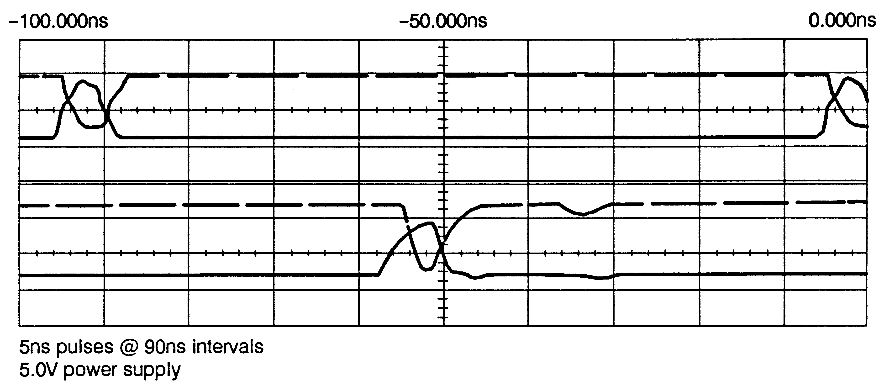
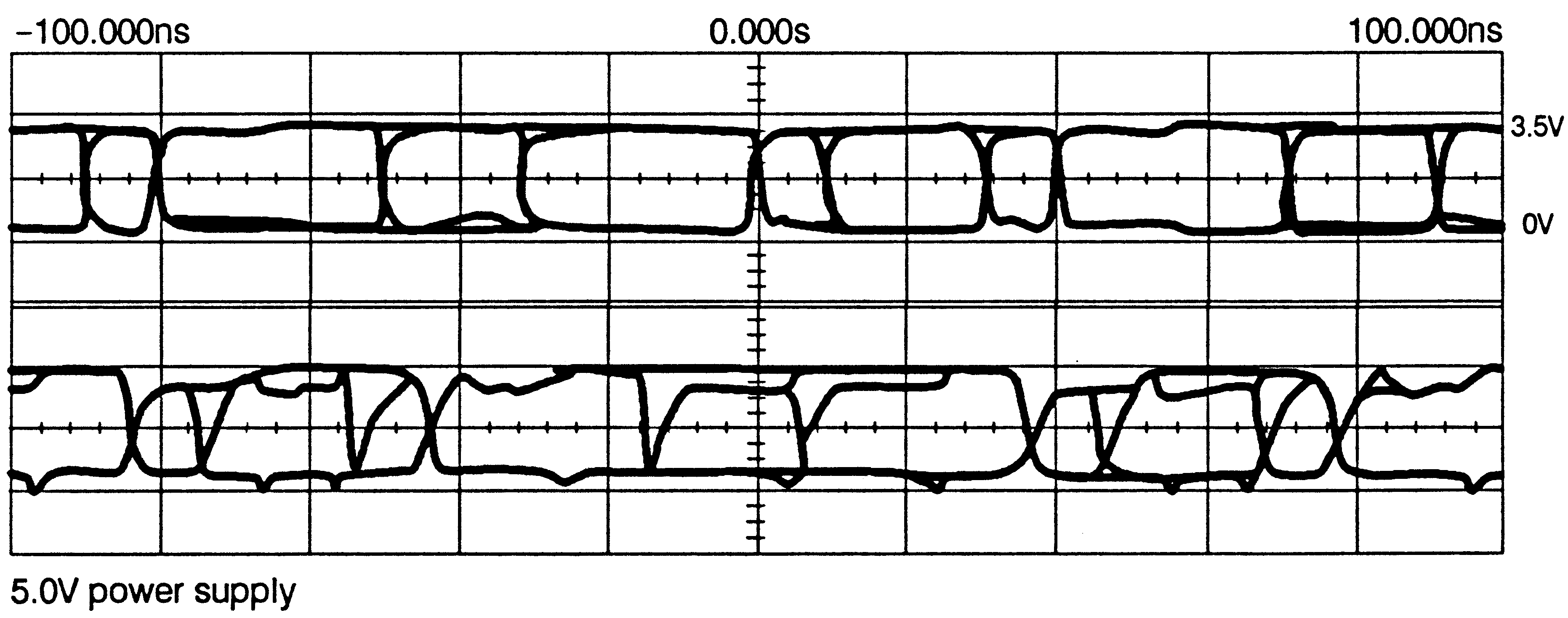
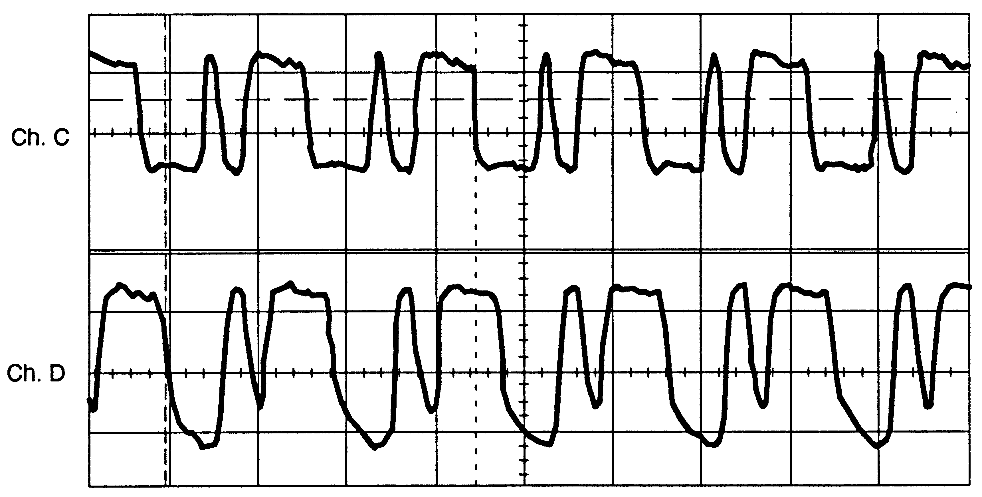
A few example ’scope traces are shown of the waveforms seen with different lengths of connection and with different forms of buffering. The waveforms on this page are from simulated link signals: figure 9 shows isolated 5ns pulses, with less than 1.5ns distortion resulting from the driver, receiver, and 10m of 30AWG cable; figure 10 shows waveforms from simulated link signals before and after transmission through 41 series buffers, the circuitry described in HP’s Application Bulletin 78, and 100m of fibre (waveforms are identical when using Honeywell optical components).
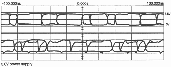
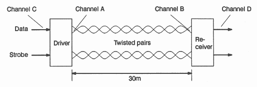
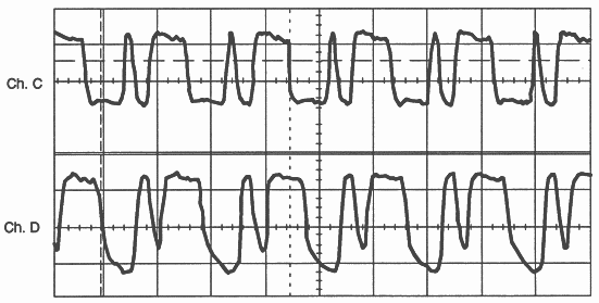
The figures 11, 12 and 13 show actual link waveforms, which were correctly received through the 41 series driver and receiver and 30m of cable.