|
|
| Using the D705B occam toolset with non-occam applications _____________________________________________________________________ |
| Andy Hamilton Central applications group, Bristol July 1989 |
There is a planet-wide plethora of existing C, Pascal, and FORTRAN software which could benefit from execution on INMOS transputers [1]. Transputers are fast, flexible, and fun. And cost-effective too. Transputers offer an unparalleled opportunity for incrementally upgradable multiple-processor solutions.
In the past, most of the available transputer software support has been centred on the occam [2] programming language, which was developed by INMOS especially for the transputer. Now, development systems for a number of popular languages are available from INMOS and third parties. These development systems can accommodate a range of target and development environments.
This document explains, in programmers’ terms, how one can use the INMOS development systems to support existing non-occam applications for execution on single or multiple transputers across a variety of hosts. For information concerning the actual modifications required to the structure of a non-occam application, in order to fully exploit the parallelism offered by transputers, the reader is directed towards [3].
This document places emphasis on the INMOS D705B occam toolset. However, VAX and Sun-3 versions of the occam toolset are available [4]. Everything shown here in relation to the D705B is also applicable to any other development platform: Three dots ... will be used to represent areas of hidden source text in any language. Hexadecimal numbers will be prefixed by the hash character ’#’. A typewriter font denotes program text (occam or otherwise). For information on the occam language the reader is advised to refer to [2]. The % symbol is used as a one character wild-card in D705B toolset file names. The term ”EOP” represents ”Equivalent Occam Process”. An EOP consists of compiled C, Pascal, or FORTRAN, with the necessary run-time library support, linked together with special occam interface code.
Many thanks to the INMOS Bristol Software Group for their assistance in the preparation of this document.
The INMOS transputer consists of a high-performance processor, on-chip RAM, and inter-processor links, all on a single chip of silicon. Program variables in on-chip RAM are accessed much faster than if they were off-chip. The inter-processor links are autonomous DMA engines, and permit any number of transputers to be connected together in arbitrary networks. The external memory interface allows linear access to a total memory space of 4 gigabytes.
The T800 and T425 transputers have 4 Kbytes of single-cycle on-chip RAM (40ns access time on a 25 MHz part), and the T414 has 2 Kbytes. The on-chip RAM is usually at least four times faster than the external memory provided with most transputer boards, depending on the hardware design of the board. The fastest external memory supported by the transputer is three-cycle (two cycle on the T801), with most boards using four- or five-cycle memory - using external RAM will not make programs run three to five times slower.
For further information on the transputer family, the reader is directed to [1].
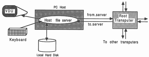
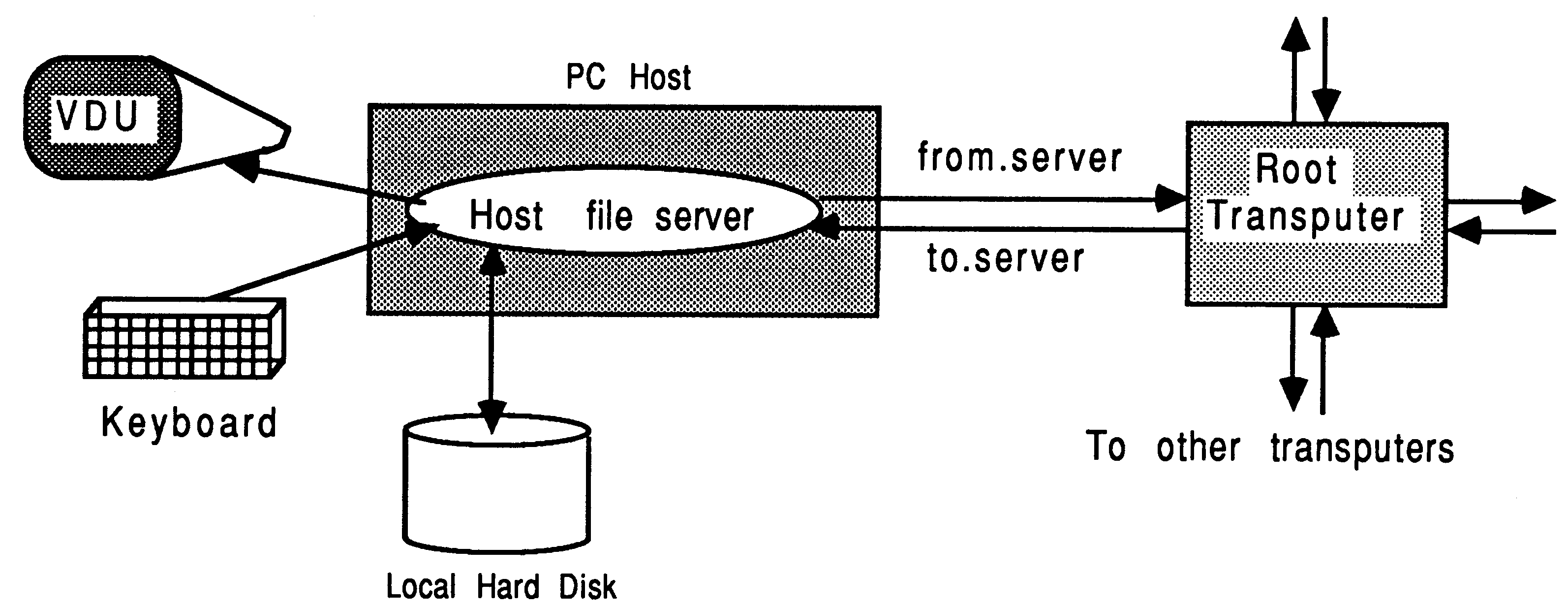
In the development environment, the transputer is normally employed as an addition to an existing computer, referred to as the host. Through the host, the transputer application can receive the services of a file store, a screen, and a keyboard. This document assumes an IBM PC or compatible host, in so far as it makes reference to some MS-DOS specific features - there are equivalents for the other toolset platforms. For a more thorough guide to product availability, please refer to [4].
The transputer communicates with the host along a single INMOS link. A program, called a server, executes on the host at the same time as the program on the transputer network is run. All communications between the application running on the transputer and the host services (like screen, keyboard, and filing resources) take the form of messages. The standard transputer C, Pascal, and FORTRAN development systems use a server called afserver. The D705B occam toolset, along with the INMOS Parallel C and Parallel FORTRAN development systems, use a server called iserver.
The root transputer in a network is the transputer connecting to the host bus via the link adapter. Any other transputers in the network are connected together using INMOS links, to the root transputer. A transputer network can contain any size and mix of transputer types.
The relationship between the transputer and the host during software development does not impose restrictions on the way the transputer is employed in the target environment.
The INMOS transputer development and evaluation boards use a triplet of signals to control and monitor the status of a transputer network connected to them. These signals are called reset, error, and analyze, and are all used in three ports called up, down, and subsystem. This allows a hierarchy of transputers in a network, where some transputer board can be given the authority to reset and analyze others.
The down and subsystem ports can assert the reset and analyze signals to control boards connected to them, and in turn monitor the error signal of the sibling board. The up port receives the reset and analyze lines from its parent board, and is used to feed back the status of the error line to the parent. On any given board, a connection is made between the down or subsystem ports to the up port on next board. If the down port is used, then both boards are at the same hierarchy. If the subsystem port is used, then the child board is at a lower level of hierarchy than its parent.
With the occam toolset, a single bootable program is created which contains code for all the transputers in the network. The host (PC) computer should have the authority to monitor and control the reset, analyse, and error signals for the whole network. Therefore, when using the toolset software to develop multi-transputer programs, all transputer boards should be connected ”down port to up port” from the root transputer outwards. If this is not done, then:
For users familiar with the INMOS Transputer Development System (TDS), the network attached to the root transputer board is normally connected to the subsystem port, rather than the down port. This allows the TDS to monitor and control a transputer network, without the risk of itself hanging up due to an execution error in the network. It should be noted however, that this type of connection is not preferred when using the toolsets.
Equivalent versions of the INMOS D705B occam toolset exist for the VAX and Sun-3 environments. These development systems contain the same components and libraries; they accept the same command line arguments and parameters, and offer compatibility at occam source and object binary levels.
This means that occam source, or compiled/linked object code can be freely migrated amongst these development platforms, and compatibility is guaranteed. So, for example, at the time of writing (April 1989), INMOS did not offer VAX and Sun-3 hosted scientific-language compilers. But C Pascal, or FORTRAN source could be compiled with the PC scientific-language compilers, transferred to a different development platform, and integrated with the rest of the application to be ultimately fully portable across the range of occam toolset development platforms.
The INMOS scientific-language compilers can be used to compile and run a non-occam application on a single transputer. They can also be used to build a compilation unit equivalent to an occam process, which can then be incorporated into a complex mixed-language system using the D705B occam toolset (or the Parallel C and Parallel FORTRAN packages).
This chapter deals only with the capabilities of the scientific-language compilers, and not with those of the D705B occam toolset.
In connection with the PC environment, the scientific-language compilers discussed in this document are:
| C | As defined in Kernighan and Ritchie ”The C |
| Version 1.3 | Programming Language”, Prentice-hall, 1978. |
| INMOS Part no: IMS D711C | |
| Pascal | As defined in BS6192:1982, |
| Version 1.2 | Functionally equivalent to ISO 7185. |
| INMOS Part no: IMS D712C | |
| FORTRAN | Based on ANSI FORTRAN 77, |
| Version 1.1 | Defined in ANSI X3.9.1978 with extensions. |
| INMOS Part no: IMS D713C | |
| Parallel C | As defined in Kernighan and Ritchie ’The C |
| Version 2.0 | Programming Language”, Prentice-hall, 1978. |
| INMOS Part no: IMS D711D | |
| Parallel FORTRAN | Based on ANSI FORTRAN 77, |
| Version 2.0 | Defined in ANSI X3.9-1978 with extensions. |
| INMOS Part no: IMS D713D | |
INMOS scientific-language compilers are additionally available for the VAX environment. Remember that binary object code produced by the PC scientific-language development systems can be integrated with the occam toolsets on a different development platform. For details concerning the current product availability and part numbers for the products, refer to [4].
Each scientific-language system offers some useful features over and above those required by the respective standard. The features common to all the scientific-language compilers are listed below:
A single transputer, single non-occam process, is the special simplest case where the occam toolset is not required. It is possible to compile and run a scientific-language process on a single transputer in as few as three commands! These systems are constructed using the pre-compiled binary object files supplied with each of the scientific-language transputer compilers, using a command structure which is similar for C, Pascal and FORTRAN applications. A transputer bootable file is one which contains enough information to allow it to be sent to a transputer (network) by the host file server, and executed. A bootable file is created by linking the compiler’s object output with various run-time support components, and prepending a bootstrap loader:
Each command shown below causes the appropriate tool to be loaded onto the transputer board, and run with the appropriate parameters. All the compilers accept their respective source-level input, and produce by default a binary object file as output. The linking command causes the compiled binary object file to be linked with the appropriate run-time library, and also with a supporting fragment of occam which is known as the ”harness”. The purpose and content of the harness is described in Section 5.
Note that the file name extensions are optional, but are included here explicitly. The filename convention for the PC environment for binary object files is bin. The scientific-language compilers can optionally produce hexadecimal object code, identified by a .hex filename extension. A .b4 extension identifies a transputer bootable file for a single transputer. Source files for C, Pascal, and FORTRAN have the default extensions of .c, .pas, and .f77 respectively.
Standard tool operation is:
| Operation | T414 target | T800 target |
| Compile | t4c prog.c | t8c prog.c |
| Link | t4clink prog.bin | t8clink prog.bin |
| Run | run prog.b4 | run prog.b4 |
Standard tool operation is:
| Operation | T414 target | T800 target |
| Compile | t4p prog.pas | t8p prog.pas |
| Link | t4plink prog.bin | t8plink prog.bin |
| Run | run prog.b4 | run prog.b4 |
Standard tool operation is:
| Operation | T414 target | T800 target |
| Compile | t4f prog.f77 | t8f prog.f77 |
| Link | t4flink prog.bin | t8flink prog.bin |
| Run | run prog.b4 | run prog.b4 |
Although the user may not be aware of it, all tools are loaded by calling the host file server. This is afserver or iserver depending on the development system. For systems using the afserver, the server is supplied with the name and parameters of the tool to be loaded. For example, the command t4c world, to compile the C program world.c, is actually doing something like this:
afserver -:b \tc1v3\tc.b4 world /t4 -:o 1
|
The -:b command is the server’s boot command, and causes the file referenced to be sent to the transputer board and executed. The -:o 1 is concerned with the workspace allocation that the compiler will use on the transputer board. This is an example of using the run-time workspace specification capability described in Section 3.8.3.
The same approach is used for the other scientific-language compilers, and for the linker. For example, the command t4clink world does the following:
linkt world.bin+\tc1v3\crtlt4.bin+\tc1v3\t4harn.bin,world.b4
|
The plus signs above represent the concatenation of the input files, and the comma separates the list of input files from the output file. The reference to linkt calls the afserver with the linkt.b4 transputer bootable linker. This adds the necessary parts from the T414 C runtime library crtlt4.bin, and the supporting harness t4harn.bin, to make a bootable file called world.b4.
For the Parallel C and Parallel FORTRAN compilers, which use the iserver, the principle is the same as above, but the boot files and server options are different.
It is straight forward to re-run the compiler and linker tools described above, without having to boot the tool onto the transputer board each time the tool is used. This is achieved by calling the afserver program directly, but without specifying the boot command (-:b filename).
As an example of this, suppose that the C compiler has been loaded onto the transputer board, and set to compile a file called c1.c for the T800, using the following command:
t8c c1
|
Then to compile separate applications c2 and c3 for the T414 and c4 to c7 for the T800, but without reloading the C compiler each time, one can use the following commands
afserver c2 /t4 -:o 1
afserver c3 /t4 -:o 1 afserver c4 /t8 -:o 1 afserver c5 /t8 -:o 1 afserver c6 /t8 -:o 1 afserver c7 /t8 -:o 1 |
Note that once a compiler has been loaded, then each time it is re-run, the afserver must be given a -:o 1 directive. This is so that when the compiler is running, it is given the maximum available memory on the transputer board for its own workspace requirements (see Section 3.8.3). For example, to compile the following three FORTRAN programs, use this technique:
t8f f1.f77
afserver f2.f77 /t8 -:o 1 afserver f7.f77 /t4 -:o 1 |
The first command here will actually load the FORTRAN compiler, and the remaining two will correctly re-run it for the different processor targets.
The same technique can be used to re-run the linker, and also applies to iserver tools.
It is possible to run any transputer executable .b4 file as if it were an MS-DOS command. This is done using the linkt.exe program supplied with all the scientific-language compilation systems. Make a copy of the linkt.exe program but give it the same root filename as the bootable .b4 program you wish to run as an MS-DOS command; keep the .exe extension.
The linkt.exe program works by taking the command verb from its command line, adding the .b4 extension, and calling the host file server afserver to load that file from the same directory as the linkt.exe was loaded from. When invoking a .b4 file in this way, the afserver is passed the -:o 1 directive automatically to give the application (if it uses the standard occam harness) one large combined workspace. It is still possible to specify the -:o 0 directive on the command line to over-ride this, ensuring the run-time stack is placed in on-chip RAM.
Each scientific-language comes supplied with two different run-time libraries. This is important when one is developing multiple-process systems. A process which expects to communicate with the host file server must be linked with the full run-time library. A process which uses only the channel communication primitives discussed in Section 3.9, plus other functions that do not require to access the host I/O facilities, can be linked with the reduced (stand alone) run-time library. This offers certain advantages in terms of code size, execution speed, and ”portability” within a multi-process system.
Each run-time library consists of separately compiled program modules. The full and stand alone libraries have many modules in common the stand alone library being essentially a subset of the full run-time library. The languages of implementation of the modules include C, IMP, and occam. The library management facilities offered by the linker permit the binary object files produced from different language compilers to be mixed together and referenced as a single entity; the library. Only those library modules that satisfy outstanding external references will be linked into an application by the linker.
At start-up, all the static workspace in the referenced modules in the run-time library is relocated from the non-occam code area to the heap workspace area. This is done because the code area could be in read only store such as EPROM, whereas the heap workspace must be writeable. The existence of this static data in some component modules prevents the run-time libraries (as a whole) from sharing the re-entrancy property that occam libraries possess.
The component object modules which were used to build each library are also supplied with each scientific language system, along with control files to allow the linker to reconstruct these libraries. This allows users to create their own libraries, add their own modules to them, and delete unused modules, to suit specific project requirements.
This section discusses the memory allocation policy used by the scientific-language compilers. An overview of the occam memory allocation strategy is given first, because all scientific-language memory allocations conform to this framework.
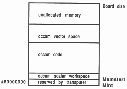
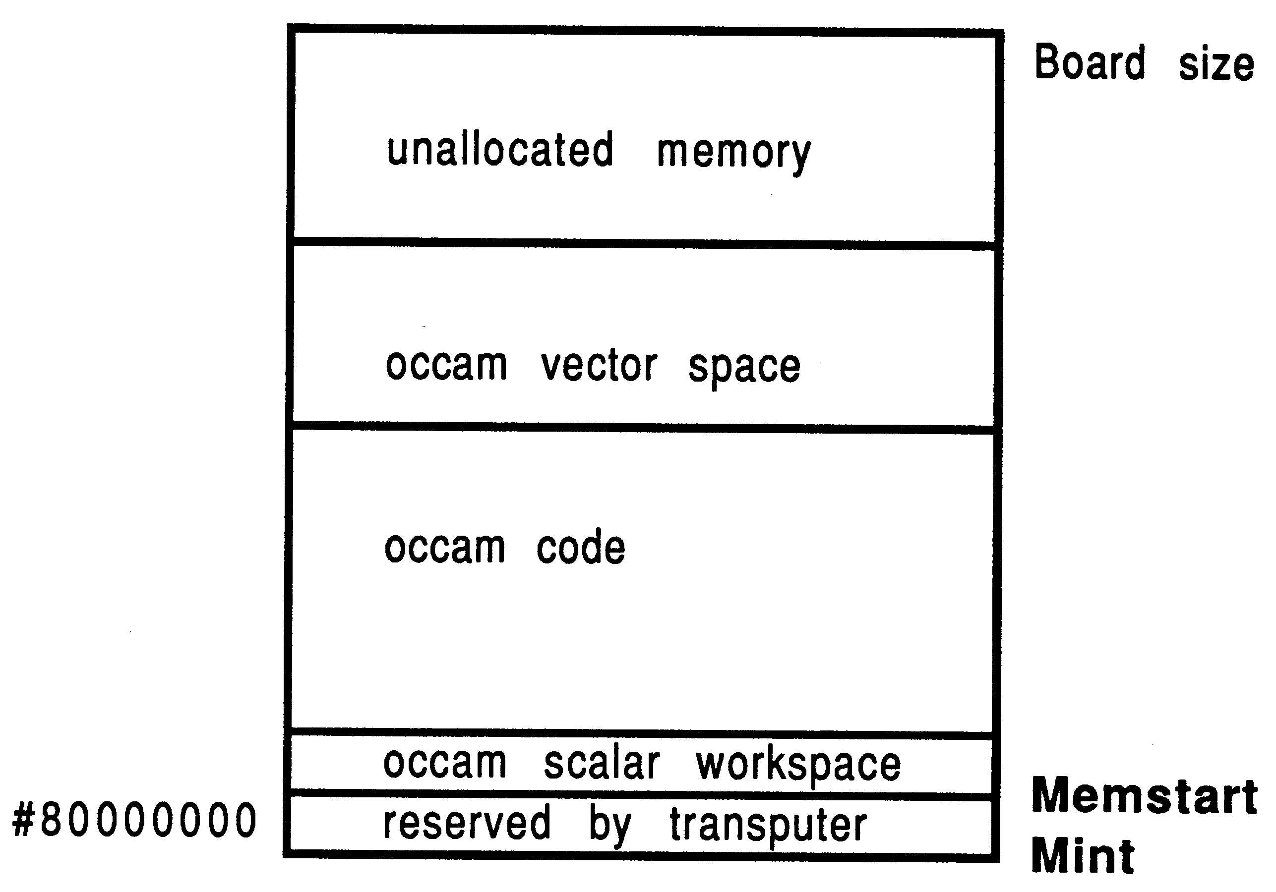
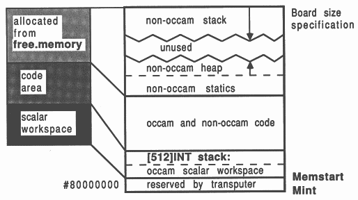
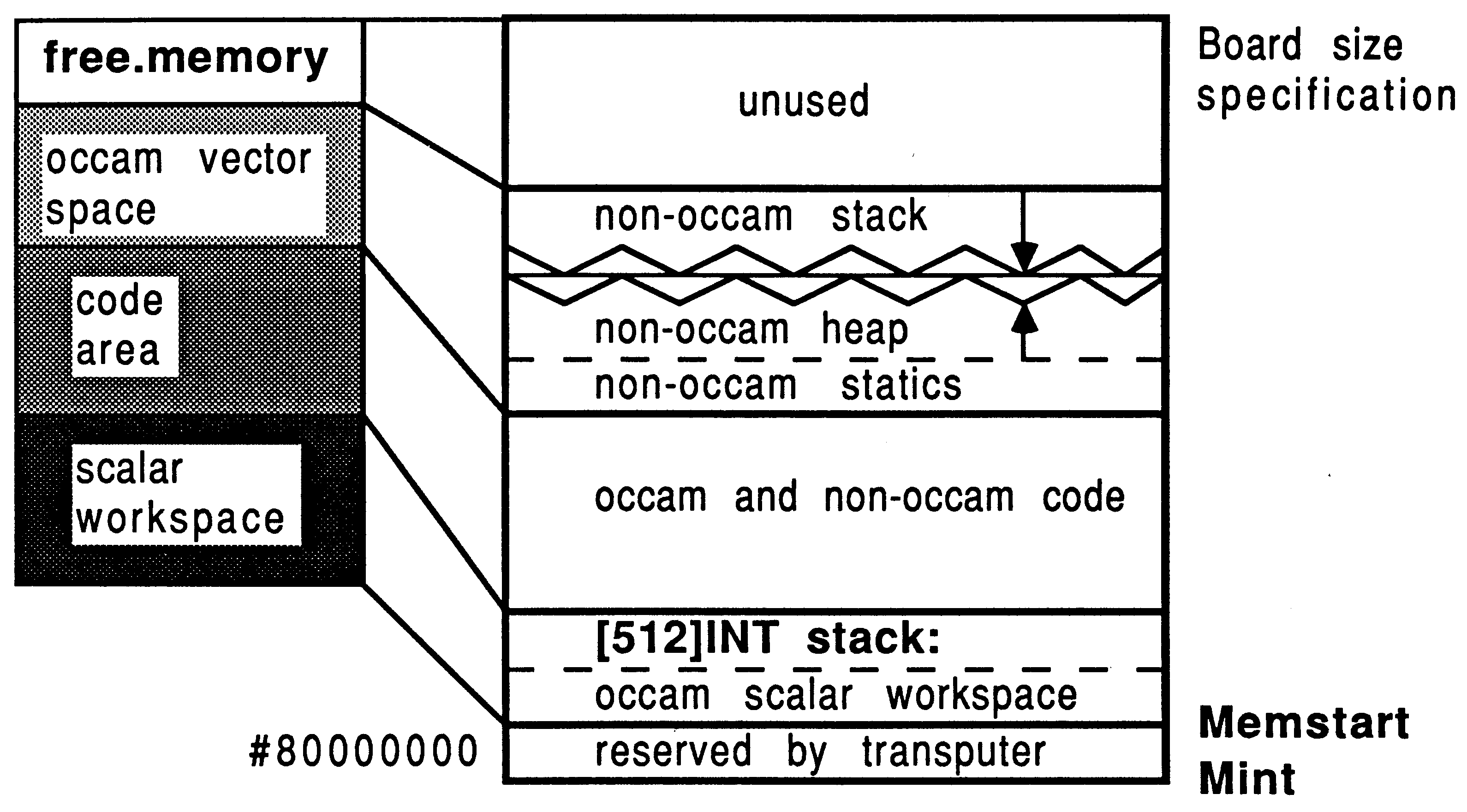
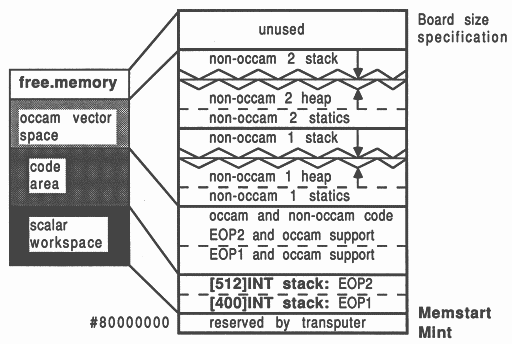
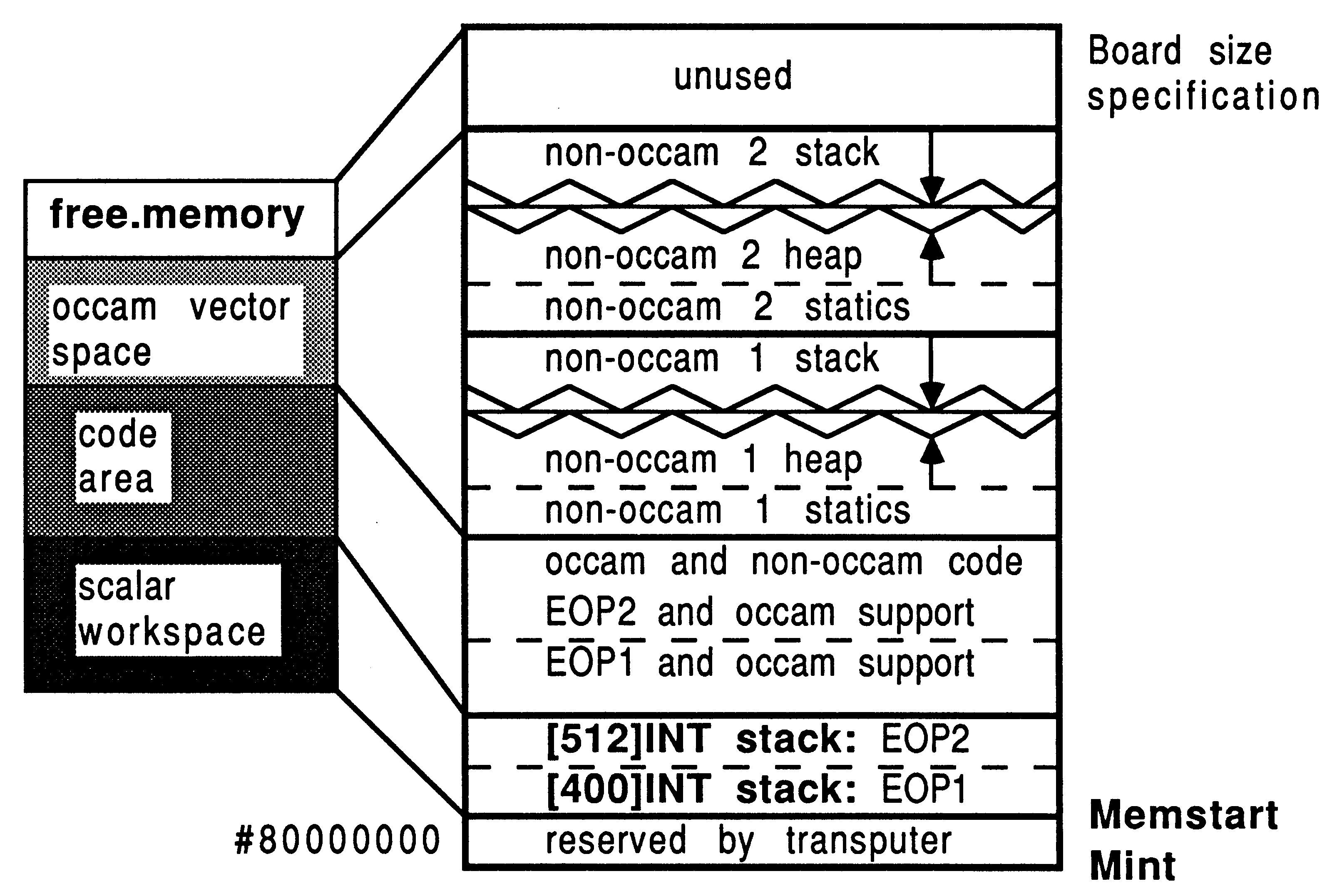
The transputer employs a signed memory address space, which for 32-bit machines begins at MOSTNEG INT (Mint) #80000000 and extends up through zero to the positive address space and onwards to MOSTPOS INT #7FFFFFFF. External memory is usually decoded at very negative addresses, because in this way it forms a seamlessly-joined contiguous block with the transputer’s on-chip RAM. Memory in a system is allocated from the most negative addresses onwards. This is shown in Figure 2.
With reference to the Figure, there are five memory zones in the memory map. Starting at the bottom of memory is an area reserved by the transputer. The first memory location in the transputer not required by the transputer itself is called Memstart. On a T414, this corresponds to address #80000048, and on the T425/T800 series corresponds to #80000070. The host file server loads the boot file, using memory from Memstart onwards.
The Figure shows that scalar occam workspace is placed as low down in memory as possible, starting in on-chip RAM just above Memstart. The occam compiler places the most recently declared variables in the lowest workspace slots.
Directly following the scalar occam workspace is the code area. This represents the concatenation of all the object files comprising the application, plus any library routines that were referenced. If any of the occam source was compiled with separate vector space on, then after the code area follows the vector space area. Above this, the memory on a transputer system is unallocated.
This memory arrangement is made possible because, in occam, all data allocation is static. This means that after compilation and linking, the loader knows exactly the data requirements of the program, for both scalar and vector workspaces.
After the boot file has been loaded by the file server, the bootstrap code does a KERNEL.RUN of the process code, and execution on that processor begins.
All memory allocation in the scientific-language systems is ultimately under the control of some standard occam specification. All memory allocation in the scientific-language systems conforms to the occam memory allocation policy described above. This fact should guide one’s understanding of the memory allocation diagrams in Section 5.4.
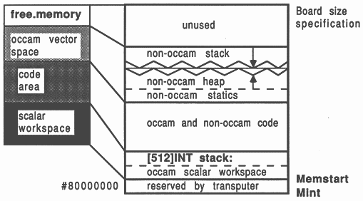
Memory for scientific-language workspace usage is allocated from an integer vector representing all the available memory left on the board once the application has been loaded. This vector extends from the top of the board memory right down to the top of the occam vector space zone. This memory area is shown in Figure 2 as unallocated memory.
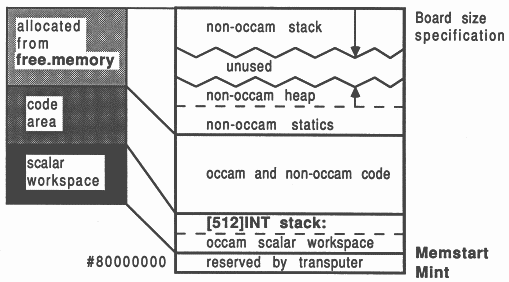
Using only the tools provided with a scientific-language compiler, a single transputer single process system can be created1. The memory allocation in this system is shown in Figure 3. This represents the memory map of the standard occam harness supplied with each scientific-language system (for creating a single process single processor system).
All the scientific-language compilers operate with two logical workspaces: a run-time stack and a combined heap and static data area. Depending on a run-time option, and various decisions made when compiling the occam support software, the physical realization of these logical workspaces varies.
Figure 3 shows this reserved run-time stack area in the occam scalar workspace zone. On a T414 transputer, this uses up all the on-chip RAM. Even if the user does not run the application to make use of this stack, this memory is always reserved when using the standard occam harness. The Figure also shows a run-time stack at the top of the memory map, and a heap lower down. Only one stack area is ever used by a scientific-language process at any one time.
These features are common to all the scientific-language compilers. Some are designed to allow good use of the transputer on-chip RAM. Others simplify the accommodation of changing development situations.
The run-time stack is known as a ”falling” stack. The stack pointer starts off high in memory and descends as space is allocated. Called functions will have their workspaces placed at lower addresses than the caller. The loader will attempt to determine the size of the target board, so it can make best use of the available memory by placing the top of the stack at the very top of physical memory.
If the user elects to use the on-chip stack (assuming it is sufficiently spacious for the application), then the space at the top of memory will not be used. If the off-chip stack is selected for use, then it is important that as the stack grows downwards and the heap grows upwards, ”never the twain shall meet”. Heap allocation requests are range checked to ensure that the stack is not about to be overwritten - but for performance reasons, this is not true of stack allocation requests. The stack can overwrite the heap area, but not the other way round. If any workspace overwriting occurs, the program will fail in unpredictable ways.
The run-time heap is known as a ”rising” heap. This means that it starts off at a low memory location and uses successively higher memory locations as data is added to it. The heap directly follows from the static data storage area. The heap is used typically for variable-length memory allocations, for items such as strings, arrays, and the dynamic commands like malloc(). Compared to the stack, allocation requests for heap space are much more infrequent, and tend to be for larger data items. This means that there is a comparatively low overhead in checking run-time requests for heap space, to ensure that the heap is not about to overwrite the stack.
Section 5.4.4 discusses ways of calculating and fine-tuning the amount of stack space and heap space to reserve for non-occam processes in multiple-process systems.
The user can select to use the run-time stack either in on-chip RAM or in external memory.
If the whole of the stack for a program can be accommodated within 2 Kbytes, then the on-chip stack can be used on either the T414 or the T800. In this case, only the heap and static data area is placed in external memory - the default assumed by the standard harness implementation. The standard harness reserves an on-chip stack regardless of whether it is used.
If the size of the stack is expected to be larger than 2 Kbytes, then the off-chip stack area is used, and the application will therefore have all its workspace off-chip. The parameter -:o 1, supplied to the afserver at run-time, specifies that all workspace is to go off-chip. Note that no action is required at compile-time or link-time to specify the location of the run-time stack. This facility should be used while developing a program, for which one is uncertain of the requirements in terms of stack size. Refer to Section 5.4.4 for details on dynamic fine-tuning of workspace requirements.
Note that the Parallel C and Parallel FORTRAN development systems operate slightly differently than described above. With these systems, the ”standard harness” does not reserve an on-chip stack area unless this is specified when the bootstrap is prepended. In this way, no on-chip RAM is wasted needlessly. Using an option on the bootstrap tool, the programmer specifies the size of a separate stack (if one is required), and this is placed as low down in memory as possible.
Some on-chip RAM can normally be used far code storage. On the 1414, using the afserver-based development systems, there is no internal RAM available for code storage. The iserver-based tools, because they don’t reserve unused stack space, do permit code storage on-chip in a T414. The T800/T425 families have at least 2 Kbytes of on-chip RAM that is not reserved for the variable stack, available as a code store. The inner tools avail even more.
The ordering of the files to link is critical for the performance of the program, because code placement on the processor is determined by the linking order of the binary object files. Programs will therefore run faster if small, speed-critical routines are placed at the beginning of the list of files to be linked, and the occam calling process is placed at the end.
It is not possible to have the whole of on-chip memory on the T800 exclusively as a stack or code area. It is also not possible to have part of the stack on-chip and part of it off-chip. This is due to the implementation of the development tools.
These restrictions on the specification of the scientific-language compilers were adopted for the following reasons. Studies showed that in the event of a trade-off in the use of on-chip memory between code and data, it is generally more efficient to permit some data to be placed on-chip (in the stack) rather than only having application code on-chip. This is due to the high density of transputer machine code, and the transputer’s hardware instruction pre-fetch mechanism. Therefore, any transputer can offer some on-chip RAM for stack purposes, but the availability of on-chip RAM for code depends on the transputer and the family of development tools.
Physically, the initialized static data area is placed at the bottom of the heap workspace area. This is placed immediately above the mixed-object code area. The size of the initialized static area can be determined at compile-time, and all the compilers generate a pre-initialized ”image” of this static data, rather than generating code to perform a run-time initialization of this area. Two draw-backs of the adopted method are that large static initialized arrays result in large binary object files, since the value of each element appears explicitly. However, in addition to this, some run-time initialization is performed by using embedded initialization information in the code output by the compiler for each module (some items cannot be initialized at compilation or linkage phases). Each static data variable has initialization data embedded in this way; a byte of initialization data for every byte of static data required by the variable.
The run-time initialization involves relocating the static data from the code area to the static/heap workspace area, and initializing it prior to execution. This is because the code area could be in read-only store.
The scientific-language systems create compilation units which can be made into an equivalent occam process (EOP). The interface to this compilation unit was devised for flexibility, and is not suitable for direct inclusion into a parallel system- it should always be wrapped in a layer of occam, described in Section 5.
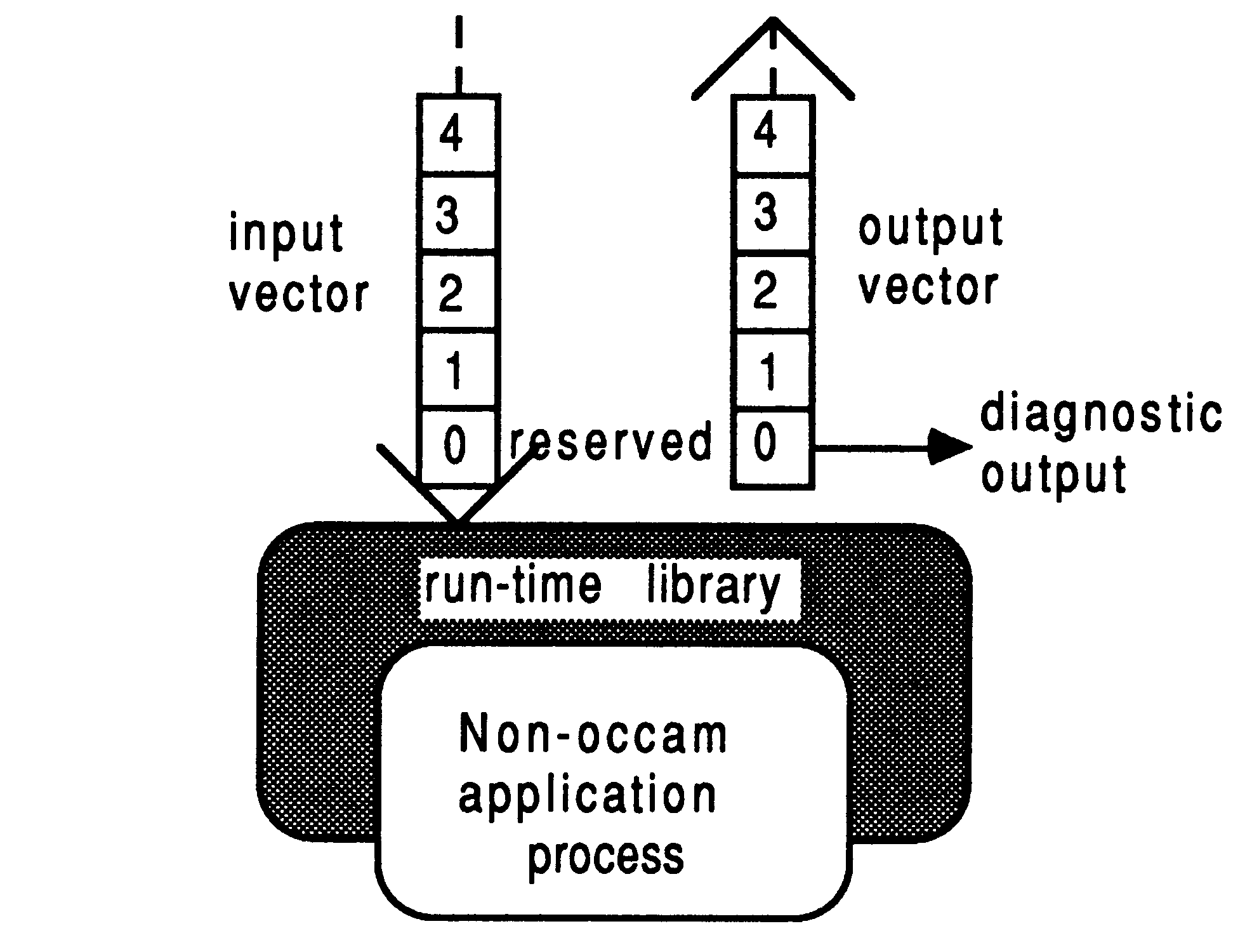
The ”raw” communications interface to an EOP takes the form of two arrays of pointers to channels. These are passed as arguments to the process by the surrounding occam environment, and consist of one array of pointers to input channels, and one array of pointers to output channels. The run-time libraries for the language involved provide access to these channels. The general interface to an EOP is shown in Figure 4.
Depending on the run-time library used with a particular scientific-language process, some elements of the channel address vector will be reserved:
Either vector of pointers to channels can be arbitrarily large, and the user is free to use them for interconnection to other processes, occam or otherwise. In general, elements 0 and 1 of the input and output channel pointer vectors should never be used by the programmer; only elements 2 and upwards should be used. Section 5 shows how best to conceal the implementation interface to non-occam components in a system, using the D705B occam toolset.
In occam, parts of an application communicate by sending messages to each other on channels. This is also true of the scientific-language implementations. Channels provide unbuffered, unidirectional, synchronized, point-to-point communications between two concurrent processes. Each scientific language is provided with four message-passing facilities by means of run-time library functions, which map directly onto the transputer’s channel I/O instructions [5]. These facilities in each scientific-language behave exactly the same as occam’s input (?) and output (!) primitives, and are outlined below
The four channel communications functions for V1.3 C are as follows:
| Command | Parameters | Description |
| _outword | w, chanp | word output |
| _outbyte | b, chanp | byte output |
| _inmess | chanp, buffer, nbytes | message input |
| _outmess | chanp, buffer, nbytes | message output |
The parameter types in the above table are as follows:
int w, nbytes;
CHAN *chanp; char b; char buffer[]; |
The C main() body is given the following arguments:
typedef int CHAN;
main(argc, argv, envp, in, inlen, out, outlen) int argc, inlen, outlen; char *argv[], *envp[]; CHAN *in[], *out[]; |
Elements of the vectors in[] and out[] correspond exactly to those described in the previous section about the scientific-language program interface.
The channel communication primitives shown above are made available by including this header file in all compilation units that perform message passing:
#include <chanio.h>
|
These examples assume that the messaging routines are called from within the main () function body, otherwise the in and out vectors declared as arguments to main() are not in scope:
int tag=0;
_inmess(in[3], &tag, 1); |
Notice that the tag is initialized to zero before the byte read. This is because only the least significant byte of the integer will be affected by the byte read, so it is advisable to initialize the whole integer to a known and sensible value before operating on only part of it.
int value;
_inmess(in[2], &value, 4); printf("%d\n", value); |
double item;
_inmess (in[4] , &item, 8); _outmess(out[3], &item, 8); |
_outbyte(2, out[4]);
_outword(3, out[4]); |
It is particularly important to notice that in the case of the _inmess and _outmess functions, the second parameter is the address of a buffer containing the actual data. If one uses the _outmess to send a word or a byte, be sure not to place a literal constant (ie, a number like 42) as the data. This should only be attempted with the _outbyte or _outword functions.
To be able to use the messaging facilities from functions outwith main(), and yet avoid passing in the channel pointers as function parameters each time, it is necessary to declare outside main () two pointers to these channel vectors. One way of doing this would be as follows:
typedef int CHAN;
CHAN **in, **out; /** This does the scoping **/ main(argc, argv, envp, topin, inlen, topout, outlen) int argc, inlen, outlen; char *argv[], *envp[]; CHAN *topin[], *topout[]; { ... usual declarations in = topin; out = topout; } |
Only now is it possible to globally reference elements of in and out from any functions other than main(). This is particularly important, because the system may appear to behave as if the channels were correctly connected, yet produce incorrect results and fail to terminate if this channel scoping is not correct.
The four channel communications procedures for V1.2 Pascal are as follows:
| Command | Parameters | Description |
| outword | w, channel | word output |
| outbyte | b, channel | byte output |
| inmess | channel, buffer, nbytes | message input |
| outmess | channel, buffer, nbytes | message output |
The parameter declarations in the table above are as follows:
w, channel:INTEGER;
b:CHAR; VAR buffer:UNIV CHAR; nbytes:INTEGER; |
These are made available by including the following file with one’s application code, and compiling the application with the /x option (which has the effect of allowing certain extensions to the ISO 7185/BS6192:1982 Pascal definition to which the compiler normally conforms):
$include ’\tp1v2\channels.inc’
|
The directory tp1v2 is the home directory for the version 1.2 Pascal compiler, so it is specified in the path for the include file.
The UNIV type of parameter, shown above in procedures inmess and outmess, provides a loophole for breaking Pascals’ strict type checking rules when passing parameters. As an extension to the ISO/BS standards, the reserved word UNIV can be prefixed to the type of a VAR parameter. This allows the parameter to be specified as a variable of any type.
The channel numbers used with these message-passing procedures corresponds exactly to those described in the previous section about the scientific-language program interface.
Some examples of Pascal channel communications in action:
inmess(2, tag, 1)
|
inmess(3, data, 4)
|
outword(count, 2)
|
outbyte(chr(5), 3)
|
The four channel communications subroutines for V1.1 FORTRAN are as follows:
| Command | Parameters | Description |
| CHANOUTWORD | VALUE, ICHANNEL | word output |
| CHANOUTBYTE | VALUE, ICHANNEL | byte output |
| CHANINMESSAGE | ICHANNEL, BUFFER, NBYTES | message input |
| CHANOUTMESSAGE | ICHANNEL, BUFFER, NBYTES | message output |
The parameter declarations in the table above are as follows:
INTEGER ICHANNEL, NBYTES, VALUE
Any FORTRAN object -- BUFFER |
It is not necessary to specify any additional information in the source text of your application (as is the case with C and Pascal) before these can be used. They are made available at link-time from the FORTRAN run-time libraries.
The ICHANNEL number used with these message-passing subroutines corresponds exactly to those described in the previous section about the scientific-language program interface.
Now, some examples of FORTRAN channel communications:
REAL*4 A
C Note that A IS 4 bytes in size CALL CHANOUTMESSAGE(2, A, 4) |
INTEGER*4 B
C Note that B IS 4 bytes in size CALL CHANINMESSAGE(2, B, 4) |
INTEGER TAG
TAG = 0 CALL CHANINMESSAGE(2, TAG, 1) |
The TAG integer is initialized to zero before reading in data to its least significant byte - the byte read will not affect the top 3 bytes in the integer, so to allow direct comparisons in this way it is sensible to pre-initialize the whole word to a known value.
INTEGER VALUE
VALUE = 1 CALL CHANOUTBYTE(1, 2) CALL CHANOUTWORD(VALUE, 2) |
It is particularly important to notice that in the case of the CHANINMESSAGE and CHANOUTMESSAGE subroutines, the second parameter is the address of a buffer containing the actual data. So ensure you never attempt to use literal constants for this parameter. For example, CHANOUTMESSAGE(2, 0, 1) will not send a byte of value 0 on channel 2 - it will attempt to decode memory at hardware address 0 and send that as a byte. Since positive address space is rarely decoded as physical memory on current production transputer boards, this is certainly wrong and could be dangerous!
Parallel C version 2.0 offers some additional message passing primitives compared to the C version 1.3. One gains access to these by inserting #include <chan.h> in the source.
| Command | Parameters | Description |
| chan_in_byte | in_b, chanp | byte input |
| chan_in_byte_t | in_b, chanp, timeout | timeout / byte input |
| chan_init | chanp | initialize a channel word |
| chan_in_message | nbytes, buf, chanp | message input |
| chan_in_message_t | nbytes, buf, chanp, t.. | timeout / message input |
| chan_in_word | in_w, chanp | word input |
| chan_in_word_t | in_w, chanp, timeout | timeout / word input |
| chan_out_byte | out_b, chanp | byte output |
| chan_out_byte_t | out_b, chanp, timeout | timeout / byte output |
| chan_out_message | nbytes, buf, chanp | message output |
| chan_out_message_t | nbytes, buf, chanp, t.. | timeout / message output |
| chan_out_word | out_w, chanp | word output |
| chan_out_word_t | out_w, chanp, timeout | timeout / word output |
| chan_reset | chanp | reset channel word |
The parameter types in the above table are as follows:
char *in_b, out_b;
int *in_w, out_w; char *buf; int *chanp; int timeout; |
For compatibility reasons, the channel messaging routines supplied with the version 1.3 C compiler are also included, and can be accessed by referencing header file #include <chanio.h>.
Parallel FORTRAN version 2.0 again offers a superset of message passing primitives compared to the FORTRAN version 1.1. One gains access to these by inserting INCLUDE ’CHAN.INC’ in the source.
| Command | Parameters | Description |
| F77_CHAN_ADDRESS | CHANWORD | address of channel word |
| F77_CHAN_IN_BYTE | IBUFF, ICHANADDR | byte input |
| F77_CHAN_IN_BYTE_T | IBUFF, ICHANADDR, TIMEOUT | timeout / byte input |
| F77_CHAN_INIT | ICHANADDR | initialize a channel word |
| F77_CHAN_IN_MESSAGE | LENGTH, BUFF, ICHANADDR | message input |
| F77_CHAN_IN_MESSAGE_T | LENGTH, BUFF, ICHANADDR, T.. | timeout / message input |
| F77_CHAN_IN_PORT | PORTNO | value of input port binding |
| F77_CHAN_IN_PORTS | -- | number of input ports |
| F77_CHAN_IN_WORD | WORD, ICHANADDR | word input |
| F77_CHAN_IN_WORD_T | WORD, ICHANADDR, TIMEOUT | timeout / word input |
| F77_CHAN_OUT_BYTE | IVAL, ICHANADDR | byte output |
| F77_CHAN_OUT_BYTE_T | IVAL, ICEANADDR, TIMEOUT | timeout / byte output |
| F77_CHAN_OUT_MESSAGE | LENGTH, BUFF, ICHANADDR | message output |
| F77_CHAN_OUT_MESSAGE_T | LENGTH, BUFF, ICHANADDR, T.. | timeout / message output |
| F77_CHAN_OUT_PORT | PORTNO | value of output port binding |
| F77_CHAN_OUT_PORTS | -- | number of output ports |
| F77_CHAN_OUT_WORD | WORD, ICHANADDR | word output |
| F77_CHAN_OUT_WORD_T | WORD, ICHANADDR, TIMEOUT | timeout / word output |
| F77_CHAN_RESET | ICHANADDR | reset channel word |
The parameter types in the above table are as follows:
INTEGER CHANWORD
INTEGER IBUFF, ICHANADDR, TIMEOUT INTEGER PORTNO, IVAL INTEGER NCHAN, ICHANADDRARRAY(NCHAN) Any FORTRAN object -- BUFF Any 4 byte FORTRAN object -- WORD |
For compatibility reasons, the channel messaging routines supplied with the version 1.1 FORTRAN compiler are also available.
The Parallel C and Parallel FORTRAN compilers have some additional capabilities to support the generation of parallel processes, and also replace the toolset’s occam configuration stage with a C-like meta-language.
Parallel C has the concept of parallel threads of execution. A C task can contain several parallel execution threads. All of a task’s threads share the same static, extern, and heap data, and therefore run on the same processor as the governing task. Each thread has its own stack for auto variables, which is allocated from the heap of the main task by using a thread_create function. A semaphore mechanism is provided to ensure mutual thread exclusion from critical shared data areas. Threads can also communicate with each other by using channels.
Parallel FORTRAN also has a multiple thread facility, but this is more restricted than in Parallel C because FORTRAN sub-programs are not re-entrant - a sub-program cannot call itself, directly or otherwise.
Using threads without due care in synchronizing access to shared data areas with semaphores can introduce errors which are very difficult to pin-point. In contrast to a thread, a task is a more substantial entity. Tasks correspond to the compilation units of the other compilers. Tasks communicate with each other only by using channels. Each task has its own code and data areas which are separate from those of all other tasks.
The Parallel C and Parallel FORTRAN configuration meta-language allows one to specify a process to processor mapping without recourse to an occam specification. The hardware topology is described in terms of processor and wire statements, which include the host PC as a processor. Each task in the network is identified with a task specification which names the task and identifies the number of input and output channels, plus specific requirements such as heap space. Tasks are allocated to processors with the place directive, and are interconnected using connect statements.
One attraction of the Parallel C and Parallel FORTRAN compilers over the occam toolset software is the flood-filling configures. This allows applications written in a particular way (a single controller task with arbitrary numbers of identical workers) to be broadcast in a transputer network to automatically take advantage of how ever many transputers happen to be present.
The Parallel C compiler is supplied with a decoder utility which can examine the binary object output from the compiler. It produces a listing showing the source code and the corresponding disassembled machine code. It can also be used on the object output of the V1.3 C, V1.2 Pascal, and Parallel FORTRAN compilers. Note that the utility cannot be used on bootable .b4 files. The utility is similar to the D705B toolset’s ilist utility.
For further information on INMOS Parallel C or Parallel FORTRAN, refer to [6, 7].
The two C compilers described earlier both support the inclusion of transputer assembler inserts. This is not documented for the version 1.3 C compiler because the implementation provided in this case is limited and can give incorrect code generation without notification (for example, if one attempts to access local auto variables symbolically). Note clearly that this facility is not supported by INMOS. The Parallel C version 2.0 offers a more flexible and correct assembler insert capability.
The use of transputer assembler should be restricted to either increasing the performance of short sections of time-critical code, or for direct manipulation of the hardware. The assembler capability in the C compilers is suitable for these tasks, but should not be seen as a means of writing large sections of code in assembler (for this a proper symbolic macro-assembler is advised). And don’t try it unless you have access to [5].
A transputer assembler insert is introduced with the asm directive. Instruction mnemonics are expressed in lower case. An example of using transputer assembler is shown below:
int loc(a)
int *a; { asm { ldl 2 ; } } |
This function was used in a large FORTRAN application [8] to return the address of a variable passed as a parameter to it. As FORTRAN passes parameters by reference anyway, it is simply necessary to load the parameter into the transputer’s A register and return. To understand why the parameter is referenced with a ldl 2 instruction, the following discussion on workspace allocation is helpful.
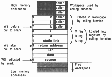
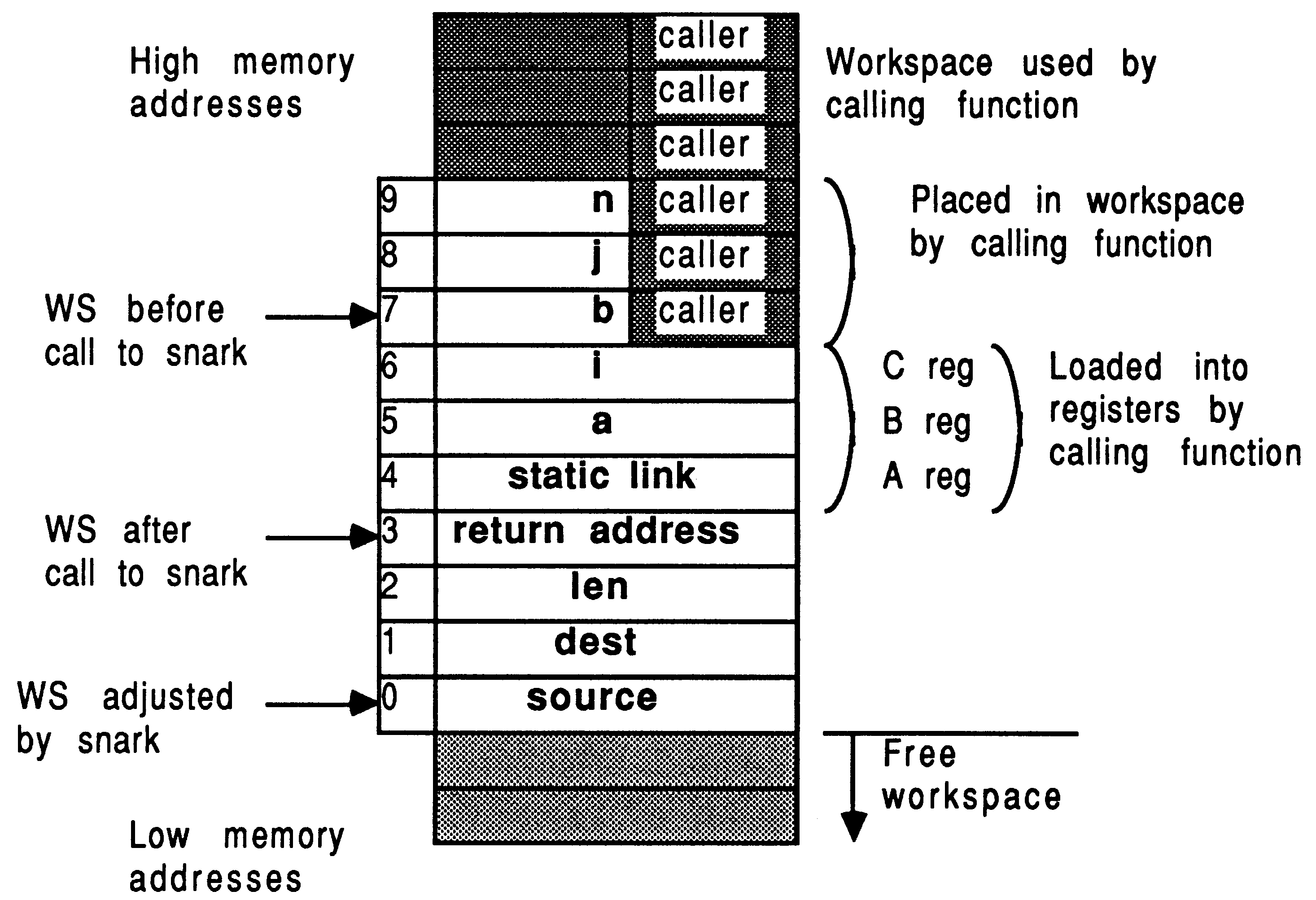
Assuming that no temporary variables are required, the transputer C compilers allocate local function workspace as follows:
If the function has no local variable declarations, then the first parameter occupies workspace slot 2. This is why the loc(a) example above used the assembler command ldl 2 to access the first parameter.
int snark (a, i, b, j, n)
char *a, *b; int *i, * j, *n; { int source, dest, len; source = b + (*j) - 1; dest = a + (*i) - 1; len = *n; asm { ldl 0; /* source */ ldl 1; /* dest */ ldl 2; /* len */ move; } } |
A function like snark is used in [8], again called from a FORTRAN environment. The reason for the -1 offset in the initialization of source and dest is to do with the subscripting incompatibilities between C and FORTRAN languages (as opposed to an obscure feature of the INMOS scientific-language systems). This problem is further compounded in higher dimensions (as Dr Who frequently observes) due to the array column/row major allocation differences.
It is instructive at this point to consider how the transputer implements a function call/return. The snark function will be used as an example to show how the parameters are set up and how the workspace is used. Figure 5 illustrates the situation.
The transputer implements function/procedure calling with the call and ret instructions. The workspace pointer is adjusted using the ajw instruction [5].
Consider the mechanics of a function call:
The V1.3 C compiler should not be used to symbolically access local variables or parameters - use the explanations given here as to where items will be placed in local workspace, and access them explicitly by slot number as in snark. Remember, the assembler insert feature in V1.3 C is not documented and not supported, so don’t expect too much from it. However, both C assemblers will handle automatically any pfix and nfix instructions required to encode large values.
The Parallel C assembler allows symbolic access to parameters and local auto variables. extern variables can also be symbolically accessed but only within the scope that reserves storage for them. Individual statements within an asm directive cannot be labelled. Reference [6] should be consulted for the implementation capabilities of Parallel C.
There are many advantages to having a non-occam compilation unit call an occam PROC, rather than call another scientific-language procedure compilation unit. Firstly, the occam PROC requires no elaborate support from a run-time library. Secondly, occam PROCs are re-entrant because they have no concept of ”writable static data”, which means that occam PROCs and any of the occam library support procedures can be shared by any number of scientific-language processes on the same transputer. Thirdly, the occam support package is more mature and robust than any of the current INMOS scientific-language development systems.
In addition to the above discussions of the scientific-language compilation systems, some additional considerations are appropriate when involving occam PROCs. These include:
These additional considerations are now explored:
A working knowledge of the data storage and parameter passing mechanisms discussed above in the context of mixed-language scientific-language systems is useful when calling occam PROCs.
Occam’s VAL parameters correspond to C’s non-pointer parameters, and Pascal’s non-VAR parameters. In addition, occam VAL parameters which do not fit into a single machine word are expected to be passed by pointer refenence. So, FORTRAN DOUBLE PRECISION real parameters would correspond to either a VAL REAL64 or simply a REAL64 parameter in occam. (Generally though, FORTRAN parameters are not in correspondence with occam VAL parameters).
C’s pointer parameters, Pascal’s vAR parameters, any FORTRAN parameters, and those parameters which cannot fit into a single machine word correspond to occam’s non-VAX. parameters.
Each scientific-language compilation unit passes, as a hidden parameter, the so-called static link pointer. This is a pointer to the static data for that compilation module. In occam this static link has to be accommodated by explicitly including a dummy integer first parameter in the formal specification of the occam procedure
PROC occamproc (INT dummy, REAL32 other.parm)
|
This PROC can be called from C, Pascal, or FORTRAN, but the caller must not explicitly use two parameters in the calling specification.
C and occam enjoy totally compatible array allocation strategies, in terms of the storage mapping function, and array index subscripting. This is definitely not true of FORTRAN, which stores array dimensions in exactly the reverse strategy to occam, with wild and wacky possibilities as far as subscripting is concerned. It is not encouraged to access multi-dimensional arrays between either occam or C, and FORTRAN. [8] shows an example of the complications involved in accessing elements in a single dimensioned FORTRAN character array, from a C function.
In occam any unsized array strides in the formal specification of the PROC are in fact included as hidden parameters, immediately following the pointer to the array parameter, in lexicographic left-to-right order of the missing strides. This means that a scientific-language compilation unit calling an occam PROC with an unsized array must explicitly include parameters to specify the each unsized dimension. For example, the following occam PROC specification
PROC occamproc (INT dummy, []BYTE other.parm)
-- dummy holds the static link -- this PROC has hidden parm for size of other.parm -- call it explicitly with an extra INT parameter |
must be called from, say C, like this:
char string [MAXSTRING];
... initialize the string occamproc (string, MAXSTRING); |
Here, it is faster and safer to pass a pointer to the whole memory block reserved for the string, rather than do a run-time strlen for example.
If the occam PROC to be called has been compiled with vector space on, then it is necessary to explicitly pass to the PROC, as the last parameter, a word vector of a size sufficient to contain the vectors used by the occam PROC. The pointer required should point to the base address of a sufficiently large contiguous memory area. This figure can be determined by using the D705B ilist utility on the compiled and linked occam .c%% file, with the /e entrypoint option; or alternatively from the compilation descriptor. Worked examples are included elsewhere in this document.
As an example, if the previous example was compiled with separate vector space on, and required 42 words of vector space storage, then the C must pass an extra final parameter
char string [MAXSTRING];
int vectorspace[42]; ... initialize the string occamproc (string, MAXSTRING, vectorspace); |
In occam timers, channels, and ports can never be VAL parameters. A timer parameter occupies no storage and so no parameter slot is reserved for it (this is also true for arrays of timers).
A CHAN type is represented by a pointer to the word containing the channel contents, which could be either a hard or soft channel.
Ports are represented the same way as the datatype for which they are a port. When a port is passed as a parameter, it is represented as a pointer to the corresponding data item.
All the discussions of occam PROC parameter arguments apply to occam FUNCTIONS, but with some additional complications. The recommendation to be given is to never directly call an occam FUNCTION from a non-occam compilation unit. Instead, call the occam FUNCTION from a stub occam PROC. Here’s why:
For occam FUNCTIONS returning a single result that can be accommodated in a single machine word, the result is returned in the transputer’s A register (on a T414 or T425), or in the floating point A register on a T800 if the result is floating point. The first case here is compatible with where the C compiler expects to find function results.
However, for occam FUNCTIONS returning more than one result or where the single result does not fit in a single machine word, there is the additional complication of where to store the multiple results. This is in fact achieved by passing hidden parameters to the FUNCTION arguments, which represent pointers to areas of memory where the results can be stored. The first three results that can be accommodated in a single machine word are returned in the transputer’s A, B, and C registers. Other results require one hidden parameter per result, and on the T800, the floating point registers are not used at all to return values if there is more than one result. Its life, Jim, but not as we know it!
These hidden parameters for FUNCTION result storage must be placed at the very start of the explicit parameter list. The problem with calling non-occam FUNCTIONS directly from non-occam compilation units is that the static link is unavoidably passed in as the first parameter to the FUNCTION. This is no good because the FUNCTION could try to use it as a results storage area.
So, if one wishes to make use of occam FUNCTIONS from a non-occam compilation unit, and since you canny change the laws of physics, the recommendation is to call the FUNCTION indirectly from an occam PROC, and use non-VAL parameters to return the results to the calling environment, thereby circumventing all the difficulties described above. You know it makes sense...
The D705B occam toolset consists of an occam-2 cross compiler, an occam-2 syntax checker, a librarian, a linker, a binary lister, a bootstrap utility, a configurer, a makefile generator, a symbolic network debugger, a simulator, and the iserver file server/loader. In addition, some support for converting TDS software into toolset format is provided.
Code produced by the D705B is compatible at source and binary levels across the PC, VAX, and Sun-3 toolset platforms. All tools display usage information if invoked with no parameters, all tools have the same ”work in progress” information selector (/i), and most can be re-run without reloading them. The file name conventions facilitate the use of automated tools to control the system generation of arbitrary transputer networks.
The remainder of this chapter discusses the D7058 product occam-2 toolset. As each tool is discussed, the filename extensions employed at each stage will be shown in brackets. The k symbol is used as a single character wild-card in these filename extensions.
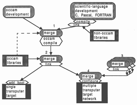
Figure 6 shows a simple overview of the software development cycle using the D705B occam toolset software. Software implementation begins at the top of the diagram, and ends at the bottom. Rounded boxes represent specific operations, hexagonal boxes identify specific tools employed, and squared boxes represent real files such as libraries. The dashed line shows that the occam compiler accesses the (proprietary and user’s) occam libraries at compile time, to check the procedure parameter interfaces across separately compiled units. The security afforded by this strict type-checking is part of the occam language specification, and is not offered by the scientific-language implementations.
In any software project, it is not possible to proceed down the diagram past any point until all the relevant operations shown above it have been done. Any operations shown horizontally adjacent can be performed at the same time. In broad terms, the software permits the occam and non-occam software for a transputer network to be developed concurrently by independent teams of programmers. At both source and binary level, the software developed will be compatible across PC, Sun-3, and VAX development platforms. A further advantage is that any development systems not available across the occam toolset development base, can still be used on their native machine and contribute binary object code for integration by the occam toolset on another platform. The D705B facilitates hooks for use with the programmers favourite version control and reconstruction software.
A typical application development scenario might look like this. Numbers refer to Figure 6. When all scientific-language source for a process is available, it is compiled and linked with run-time support. Once all such scientific-language object is available for a single transputer, and all occam source is available for that transputer, (point 1 in the Figure), the occam compiler is invoked. Immediately afterwards, at point 2, the toolset linker resolves external occam references by reading in the occam libraries specified, and merging all required code into a single object file that represents the process that runs on that transputer (point 2). Only when this has been done for each unique transputer (point 3) can the system as a whole be realized (point 4).
In real-life, for a large project, one would place pre-compiled and pre-linked compilation units (derived from any language) into libraries that could be used by other parts of the system. One would also employ structured and methodical validation and verification techniques to components before bonding them together. The toolset’s support for teams of programmers facilitates all stages of software implementation.
Because it is expected that teams of developers could be working on the same project, across potentially several development platforms, it is important to have a clear convention for identifying the contents of each file. This is achieved by using a homogeneous set of filename extensions. Because of the sophistication of the D705B, this requires a sizeable range of filename extensions, shown in the next section.
The file name extension convention for the D705B is extensive. For some files, the last two filename extension positions are dependent on the processor type and the error mode, explained in Sections 4.3 and 4.4.
| File extension | Contents |
| .occ | occam source |
| .inc | include file of protocol or constant definitions |
| .t%% | separately compiled object code |
| .l%% | linker indirect command file |
| .c%% | linked code unit |
| .s%% | linker symbol table |
| .m%% | linker code map |
| .b%% | bootable code file for a single transputer |
| .d%% | descriptor file for a single transputer |
| .r%% | single transputer code with no bootstrap |
| .lib | library file |
| .lbb | librarian build command file |
| .liu | library usage file (describes library nestings) |
| .pgm | occam configuration description file |
| .map | configuration map |
| .dsc | configuration descriptor |
| .dmp | memory dump file |
| .btl | link bootable file for transputer network |
| .btr | ROM bootable file for transputer network |
Don’t be put off by this horrific-looking table - its really seductively powerful once familiar. Simple calculation shows that there are over 200 different possible filename extensions, although not all of these are likely to materialize in a single project.
A word of advice: stick to these file name conventions, and be explicit with the filename extensions wherever possible. This will give you the maximum support from the automated system makefile generator (imakef).
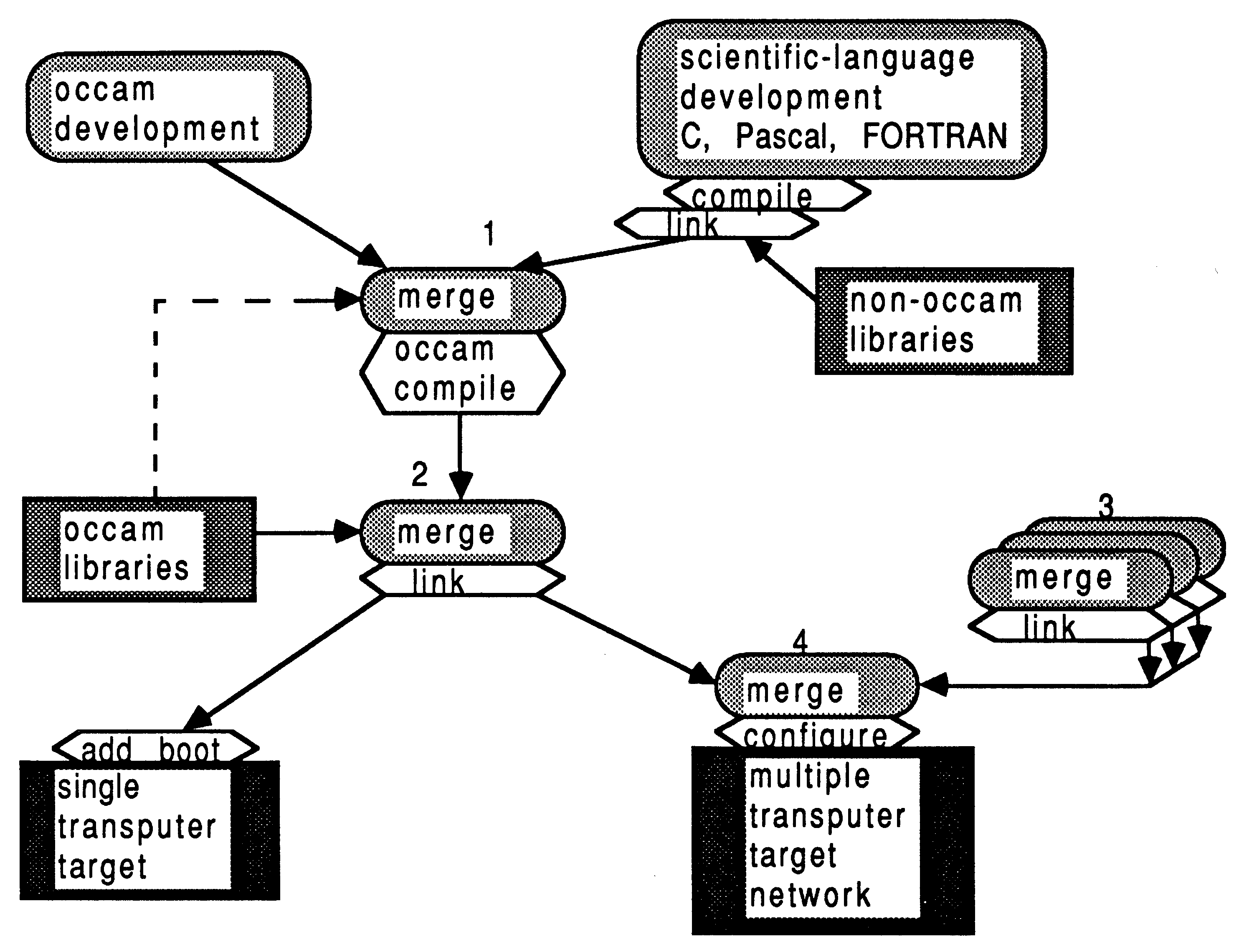
The compiler can produce code for the T212, T222, T414, T425, and T800 transputers. While all transputers are compatible at the occam source level, some transputers are additionally guaranteed compatible at the binary T-code level, This compatibility is determined by the intersections of their instruction sets. To this end, the compiler can produce code that is guaranteed to run on a set of transputers:
| Code set | Compatible processors |
| TA | T414, T425, and T800 |
| TB | T414 and T425 |
| TC | T425 and T800 |
The source restrictions on what can be compiled in each code set are determined by the instruction set intersection of the code class. Code set TA cannot contain any floating point, CRC, or 2D block-move. Code set TB can contain floating point (implemented in software by libraries), but not CRC or 2D block-move. Code set TC can support CRC and 2D block-move, but not floating point. Providing that the code produced for the different processors in a class would be the same for a given compilation unit, then that unit can be compiled in that class. All the 16-bit transputers (T212, T222, and M212) share the same instruction set, so the compiler makes no distinction.
These code sets are illustrated in Figure 7, which also shows the relationship between the processor classes and the basic processor types. The diagram shows that code compiled for processor types lower down in the tree can call code compiled for processor types above them and connected to them (possibly indirectly) by an ascending line. For example, T414 code can call T414, TB, or TA code, but TA code can only call other TA code.
To identify which processor (class) a given piece of code has been compiled for, the table above uses the % in the second position of the filename extension to indicate the processor type, which is one of 2, 4, 5, 8, a, b, and c.
If you compile code for any transputer class other than TB, the use of the compiler maths libraries must be disabled with the /e compiler option. This is because the compiler maths libraries are significantly different between the floating point T800 transputer, and the non-floating point transputers which are represented by class TB. So, classes TC and therefore TA encompass the floating-point and non-floating-point transputers, and therein lies the problem. The main differences arise because the T800 implements directly as instructions many functions which are represented as library calls for non-floating point transputers.
A further advantage of processor class compilation is that resultant libraries using generic code can be considerably smaller while still supporting a processor range. This technique will help to reduce the software size overheads of supporting present-day and future more powerful processor types.
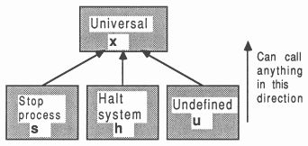
The compiler can produce code with differing behaviour when run-time errors occur. There are three error modes, suitable in different cases:
| Error mode | Behaviour on error | Identity |
| HALT system | Total system halts | h |
| STOP process | Only errant process stops | s |
| UNDEFINED | Arbitrary effect | u |
These are referred to as HALT, STOP, and UNDEFINED (REDUCED), and are identified with the letters h, s, and u in the last position of the filename extensions shown previously.
Each error mode is suitable in different situations.
This mode is used in conjunction with a halt-on-error bootstrap, and run with the iserver’s /se error test parameter.
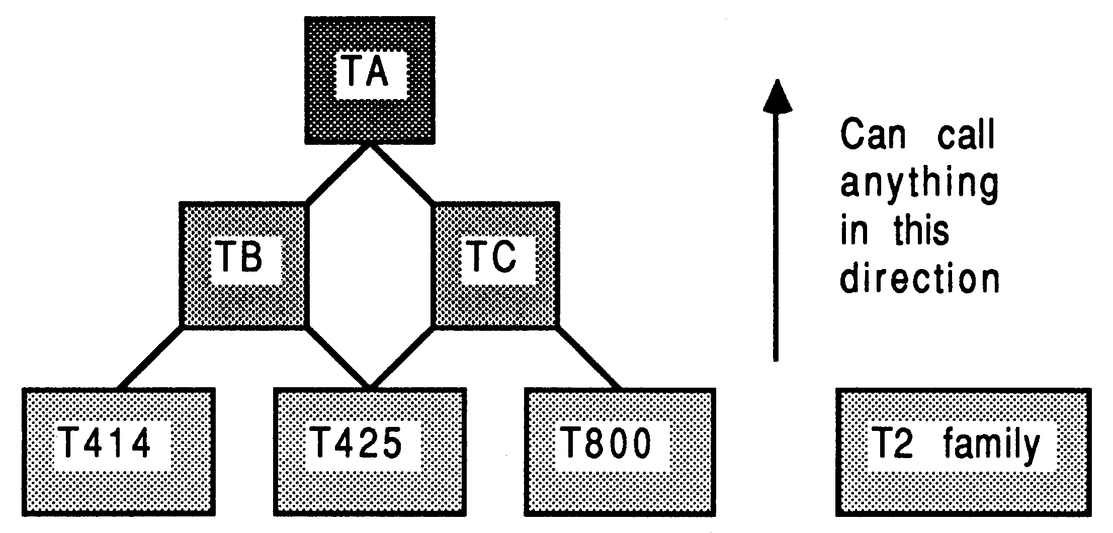
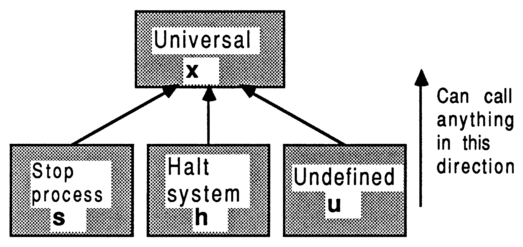
There is an additional error mode called UNIVERSAL, identified by x. This is implemented in the same way as UNDEFINED, with minimal checking. Separately compiled units compiled in this mode can be called from units in any of the other error modes, and may call other units compiled in x mode. This is shown in Figure 8. The general rule is that all separately compiled units must be compiled in the same error mode. These error modes are described more fully in [2].
If code is to be compiled in UNIVERSAL error mode, use of the occam compiler’s libraries must be disabled with the /e option, This is because the compiler libraries exhibit different behaviour in different error modes, so it is not possible to use floating point, extended data type and other compiler library functions with the UNIVERSAL error mode.
The imakef utility automatically generates a makefile to rebuild a multi-transputer program, a single transputer program, or a library. The C source is supplied so that users can adjust the program for similar tools. The program will also generate linker command files and library usage files. The program does not produce any rules for object code that has been imported using the #IMPORT occam compiler directive, although it does assume that any linked code referred to is derivable ultimately from occam source files.
The compiler occam is a full occam-2 compiler, supporting FUNCTIONS. Occam source is placed in .occ files, and compiled object is stored in .t%% files.
The #USE directive is used to reference separately compiled units from within occam source text. The imakef utility ensures that certain rules surrounding #USE are observed, in connection with non-circularity of references, compilation before usage, and compatible processor types and error modes. The default suffix with #USE is .t%% for compiled units, depending on compiler options, and .lib for libraries.
The #SC references a separately compiled unit, and is included only for compatibility with the INMOS TDS. It is recommended that the #USE directive is instead employed to reference separately compiled procedures, as this removes the constraint on specific ordering of separately compiled units at link time. (SCs must be linked in a special order because the occam compiler generates direct calls to the SCs, rather than allowing the linker to patch them. To do this, the compiler must assume they are loaded in a specific way). Simple substitution of the directive #USE for the #SC directive is sufficient.
The #IMPORT directive takes the filename of the compiled and linked non-occam application, to allow the imakef utility to handle non-occam aspects of a system. This also serves to conceal unpleasant detail concerning the instantiation of non-occam processes, while presenting to the occam compiler something that looks like an occam PROC.
An additional #COMMENT directive allows a comment string to be associated with the compilation unit, intended to hold the version number, date of last udpate, and a short description.
The directory path in which a referenced file resides can be specified explicitly, or relative to the directory in which the compiler was invoked, or have no path specified. It is strongly advised, especially in multi-platform toolset development, that no directory path specifications are ever included in occam source directives. This would have the effect of compromizing the source-level portability amongst platforms on the Sun-3, VAX, and PC. To circumvent this, a sequence of directory paths which will be searched can optionally be specified by using the PC environment variable ISEARCH. There are equivalent path specifications in the other toolsets, and these should represent the only host-specific parts of toolset development.
The default is to compile occam for a T414 in HALT-system compilation mode, with separate vector space, alias and usage checking enabled. This gives a .t4h object file.
The occam compiler stops when it detects the first error. At times, it is more useful to have. a list of errors available to permit bulk editing operations on virgin source. The syntax checker icheck generates such a list of errors, and has particularly good error recovery due to the fixed format of the occam language.
The librarian ilibr is used to collate separately compiled units into a single library file (.lib). Libraries can be built from units compiled for mixed processor types and error modes. They provide a convenient unit for distributing collections of procedures and functions in a single file. Libraries form the basis for the selective loading mechanisms of the linker (The linker will selectively load separately compiled units from a library only if they satisfy an outstanding reference and match the processor type and error mode requirements). Indirect files can be used to list the names of files to be included in the library.
A specification describing what object files have to go into a library is provided in a .lbb file. One can specify compiled object and linked object files, for a range of processors and error modes. Note that it is not possible to mix source and object in the same file, so for example it is not possible to have occam source INCLUDE files in a library.
The librarian also supports building libraries from units compiled with the scientific-language compilers. Occam procedures and functions are re-entrant and can be shared, through libraries, by separate parallel threads of execution on a single processor. As not all modules in the scientific-language libraries are reentrant, the libraries as a whole are not re-entrant. This requires that separate copies of the libraries are linked with each scientific-language process.
Libraries may reference other libraries, but may not reference code via a #SC directive. This is because the positioning of SC code is critical, whereas the library mechanisms locate code in arbitrary places. The librarian ensures the integrity of the library by checking each new addition for violation of uniqueness of processor type and error mode within the library.
The linker ilink composes a collection of separately compiled units, (.t%% and bin and .c%% linked units) resolving external references, to give a single code unit (.c%%). This is typically used to build the program code for a single processor. The output of the linker is in the form of a separately compiled unit, like that produced by the occam compiler, which means that linker output can be re-submitted as input at a later linking stage.
The first argument in the link list is always a separately compiled unit, not a library. This defines the processor target type, error mode, and entry point for the linked unit, and all further units must be compatible with respect to this processor target (set) and error mode.
Separately compiled units in the argument list are loaded unconditionally, but units in libraries are loaded only if they match the processor type and error mode of the first argument, and if they satisfy some outstanding reference. The processor target rule specifies that units may call units with at least as general target set (so T800 units can call TA and TC units, for example). The error mode rule is that units may call units with at least as general error mode set (so HALT, STOP, UNDEFINED, and UNIVERSAL may call UNIVERSAL, but HALT may only be called from HALT).
If the #SC directive is used to reference separately compiled units, then these units must be linked in the correct order. The imakef utility will generate the linker command file to achieve this correctly.
There are some restrictions as to how the linker can be used with scientific-languages. Only complete scientific-language programs can be linked using the linker - this is because the linker has to resolve the initialization chain for the scientific language compilers. To do this, it has to associate an entry point name with the output file it produces, and this is only meaningful for a complete scientific-language process. Multiple scientific-language processes to run on a single processor may be individually prelinked with run-time support and resubmitted to the linker with the main occam calling process.
Linker control input may be re-directed from a specified file or standard input. However, re-directed linker command input may not itself be re-directed. Therefore, an indirect file may not refer to another indirect file or to standard input. Several indirect files can be specified on the linker command line. Command options can be placed in the linker indirect file, for example, to optimize the positions of certain symbols.
The binary object listen ilist is used to generate documentation information from binary files, either from separately compiled units or from library files. Various command-line options permit different types of documentation to be produced. The options are accumulative, so that more than one type of output can be requested with a single command. Information concerning modules, procedures within them, entry points, processor types and error modes, external references, and workspace requirements can be extracted from any binary object file (.bin, .lib, .c%%, .t%% etc).
The iboot utility prepends bootstrap and loading code to a program for a single processor. The input file will have been produced by the linker (. c8%), and the output file can be executed on a transputer (.b%%) using the server (iserver). The default bootstrap will halt the processor if the transputer error flag becomes set. Optionally, the bootstrap will not halt the processor if the transputer error flag becomes set.
If the execution mode of the input object file is either HALT or STOP process, then the halt-on-error flag is set by the bootstrap code; otherwise the halt-on-error flag is not set in the bootstrap loader code. This, in conjunction with the type of bootstrap prepended, defines the program’s behaviour if the error flag becomes set.
The iconf configures is used to create multi-transputer programs (.btl or .lots), specified in a configuration description (.pgm), by using output from the linker (.c%% files). The configures generates loading and bootstrap information for a transputer network of arbitrary topology and composition. The bootstrap and loading information is complex due to the possibility of different transputer types in the network, each with potentially different amounts of memory.
The toolset configures allows multiple processes to be PLACEd at configuration level. In addition, any occam that does not involve library references can be expressed at configuration level.
Network description information (.dsc) is also created for use by the debugger tool.
The toolset debugger idebug allows a symbolic post mortem analysis of an arbitrary transputer network. Facilities exist to examine the contents of memory symbolically and in many different representations. The processes on the run-queues and timer-queues can be identified. It is possible to symbolically ”walk down links” to processes operating at different ends of a channel (whether soft or hard). The debugger will locate to the source line at which the transputer error flag became set, allowing variable inspection. The procedure calling sequence can be traced back, also through libraries.
In the case of scientific-language debugging, the debugger can locate to the source line at which the transputer halted. This is possible in a mixed language system of arbitrary complexity. It is not possible to use symbolic debugging facilities in scientific-language source file because the scientific-language compilers do not produce sufficient information for the debugger. However, procedure trace-back is still possible within this framework.
Later sections in this document discuss how best to use the debugger with scientific-language systems.
The toolset simulator isim can run almost any program that can be run on a single T414 transputer, on a boot-from-link evaluation board. The simulator provides most of the symbolic debugging facilities provided by the toolset debugger, plus the ability to set break and watch points at source level, and single-step a program. An important feature of the simulator is that the compiled code is exactly that which can be booted onto the transputer board and run normally.
Unfortunately, the simulator cannot accommodate non-occam components. The simulator is not discussed further in this document.
There are a number of utility tools supplied with the TDS which are also supplied with the toolsets. In particular, the tools for EPROM and memory interface programming, and the transputer network tester, are provided.
The previous sections have presented information concerning the INMOS scientific-language systems, and the D705B occam toolset. Now, this information will be combined to show how to correctly integrate non Occam processes within an occam framework. The methodology of arbitrarily interconnecting non-Occam processes is known as equivalent occam process technology (EOP).
The scientific-language systems create processes which can be made equivalent to an occam process. The interface to these processes was devised for flexibility, and is not suitable for direct inclusion into a parallel system. The language-independent interface affords a general bilateral communication between a scientific language process and an occam process, while accommodating a certain flexibility in the workspace arrangements. It should always be wrapped in a layer of occam which exposes only conventional occam channel parameters to the outside world.
There are three basic forms of equivalent occam process (EOP) which can be built
To form an EOP from a C, Pascal, or FORTRAN program, the object modules comprising the program (including the run-time library) are linked with special occam interface code, using the toolset linker ilink. These interfaces conceal various supporting details, and offer a fixed language-independent interface to occam. INMOS supplies interface code for the three types of EOP described above.
A Type 1 interface is used for programs communicating only with the host server iserver. This is equivalent to the standard occam harness used by the scientific-language development systems. The Type 1 interface has the following parameters:
PROC MAIN.ENTRY (CHAN OF SP fs, ts,
[]INT free.memory, []INT stack.memory) |
The channels fs and ts communicate from and to the host server iserver, using the protocol SP defined in a standard library (not shown). The free.memory vector is used as program workspace. If the size of the stack.memory vector is zero, then free.memory is used for the run-time stack, heap, and static workspace. Otherwise, the free.memory is used for heap and static workspace. The DOS environment variable IBOARDSIZE specifies the size of free.memory; it’s read at run-time by the bootstrap loader. The stack.memory is used as run-time stack storage if the size of the vector is not zero. Its size is determined when the bootstrap is prepended by the iboot tool, using the /s option.
The code for MAIN.ENTRY is contained in the files mainent .c%%, depending on the transputer type and error mode required. The programmer does not have to write any occam for this interface.
To use this interface, consider the following example to build a T414 program in UNDEFINED error mode. A list of compiled program object binaries (including run-time libraries) is placed in the linker control file proglink.l4u. The required linked output is to be placed in file cprog1.c4u, then bootstrapped with a 512 word run-time stack vector. The D705B operations required are:
ilink mainent.c4u /f proglink.l4u /o cprog1.c4u
iboot cprogl.c4u /s 512 |
A Type 2 interface is used for programs communicating with other processes as well as the host server. This interface is used with non-Occam programs linked with the full versions of their run-time libraries. The Type 2 interface has the following parameters:
PROC PROC.ENTRY (CHAN OF SP fs, ts,
VAL INT flag, []INT ws1, ws2, []INT in, out) |
The channels fs and ts communicate from and to the host server iserver. The flag is used in conjunction with the workspace vectors ws1 and xs2. If flag is zero then ws1 is used as the run-time stack and ws2 is used for statics and the heap. If flag is 1 then ws1 is used as a combined stack/heap/static workspace. Vectors in and out are used as pointers to occam channels going to and coming from the non-occam process.
The code for PROC.ENTRY is contained in the files procent.c%%, depending on the transputer type and error mode required. To use this interface, a simple occam harness of the type below is written to bind the channels used by the server and the other processes to a clean procedural interface:
PROC p.EOP2 (CHAN OF SP fs, ts,
CHAN OF ANY from.outside, to.outside) #IMPORT "cprog2.c4u" [3]INT in, out: [1024]INT stack.vector: [5000]INT heap.vector: SEQ -- establish user input and output channels LOAD.INPUT.CHANNEL (in [2], from.outside) LOAD.OUTPUT.CHANNEL(out[2], to.outside) -- EOP2 is the entry point name in cprog2.c4u EOP2(fs, ts, 0, stack.vector, heap.vector, in, out) : |
The #IMPORT command references the file name containing the linked EOP object binary file, its run time library, and the Type 2 interface code. The channel pointers are initialized using the predefines LOAD.INPUT.CHANNEL and LOAD.OUTPUT.CHANNEL. 1024 words have been allocated for the stack, and 5000 words for the heap/static area. EOP workspace is required by the scientific-language process and the run-time libraries, and must be large enough for all of the run time stack, static data, and the heap used by the program and its libraries. As a rough guide, a minimum of 4000 words for static & heap workspace, and a minimum of 400 words for the run time stack, is advised. By the time an EOP is ready to commence, having been through the initialization sequence controlled by the run-time library, almost 100 words of stack space have already been used.
It is important to emphasize that this occam harness is completely standard for a Type 2 interface. In the last line in the example above, the EOP2 is the substituted name for the PROC.ENTRY defined. The name-change occurs at link-time, allowing any number of EOPs in a system to use the same interface code:
ilink EOP2=procent.c4u /f proglink.l4u /o cprog2.c4u
|
This has the effect of creating a linked file called cprog2.c4u which is #IMPORTed into the occam harness above. From there onwards, the procedure p.EOP2 is considered as a standard occam procedure in the system - but it must always connect to the server.
A Type 3 interface is used for processes that do not need to communicate with the host server. There are three types for use with C, Pascal, or FORTRAN programs linked with the reduced version of their run-time libraries:
PROC PROC.ENTRY.RC (VAL INT flag,
[]INT ws1, ws2, []INT in, out) |
PROC PROC.ENTRY.RP (VAL INT flag,
[]INT ws1, ws2, []INT in, out) |
PROC PROC.ENTRY.RF (VAL INT flag,
[]INT ws1, ws2, []INT in, out) |
Another Type 3 interface is used with C, Pascal, or FORTRAN programs that have been linked with the full version of the run-time libraries. This is called the stub interface. Normally, EOPs linked with their full run-time library would require a connection to the host server, preventing their use in a ”remote” position. But the stub interface obviates this.
PROC PROC.ENTRY.STUB (VAL INT flag,
[]INT ws1, ws2, []INT in, out) |
These interfaces take parameters with the same meaning as the Type 2 interface. Depending on processor and error mode, the C interfaces are stored in files procentc.t%%, the Pascal interfaces are stored in files procentp.t%%, and the FORTRAN interfaces are stored in files procentf.t%%. The stub interfaces are in procents .c%%. They are used in exactly the same way as the Type 2 interfaces. A simple template harness is written (exactly the same as for the Type 2 interface, but without the server channels), and the linker is used to change the entry-point name. For example, a Pascal program for a T800 in HALT error mode, to be instanced with the identifier EOP3 would be linked as follows:
ilink EOP3=procentp.t8h /f proglink.l8h /o pprog3.c8h
|
The corresponding #IMPORT for this would refer to file pprog3.c8h. An example of a Type 3 EOP is given in Section 7.2.4.
The most common arrangement in a multi-process system is for one Type 2 interface (communicating with the server), and the remainder are all Type 3.
Concerning scientific-language processes, the EOPs cannot be compiled for a general processor class (ie TA, TB, TC), and therefore cannot be called by code compiled for a general processor class. This has an implication for library usage. For example, TA Occam harness code cannot call T414 EOP code. TA code can only call TA code. So, if one wishes to place occam harness parts into a library as well as the linked EOPs, they must be compiled for either T414 or T800 execution.
Each time an EOP is instantiated, there is a timing penalty to be paid. The nature and magnitude of this penalty depends on whether the non-Occam process is using the host file server facilities provided by the full run-time library, or whether the EOP is using the standalone run-time library for the language concerned. In either case, the EOP instantiation overheads are enormous compared to calling an occam procedure. An understanding of these penalties is useful in deciding how finely to partition a non-Occam system into individual parallel processes. Both these cases are discussed below:
On a 20 MHz transputer, the time taken for an EOP to startup to be in a state capable of doing useful work varies from 25 to 40 mifli-seconds, depending on the language. The start-up overheads in this case are partly concerned with run-time initialization of static data for each module in the EOP. Also, the start-up routines attempt to open the standard input, output, and error channels to the keyboard and screen. This involves dealing with the host file server, and accounts for the bulk of the time spent for most reasonably sized EOPs. This is clearly not the sort of thing to do too often - once an EOP is running, don’t terminate it with a view to restarting it regularly!
There is also a timing penalty in shutting down an EOP. This is usually of lesser consequence than the startup overhead. In the shutdown period, any open files and streams are closed, which again involves dealing with the host file server. This is again typically 25 to 40 milliseconds, although it can be less than 10 milliseconds in unusually trivial cases.
For an EOP using the standalone run-time library, none of the penalty associated with communicating with the host file server is incurred. This typically results in start-up and shut-down penalties an order of magnitude smaller than those using the full run-time library. In other words, expect to spend between 1 to 4 milliseconds in starting and stopping each EOP in this way.
A corollary of this is that EOPs should only be used to perform fairly sizable units of work, compared to the overheads in instantiating and terminating them. It is important to be quite dear that once instantiated, the operation of the normal function 1 procedure 1 subroutine calls in EOPs is every bit as efficient as for compiled occam. Calling an embedded heterogeneous compilation unit from within another compilation unit incurs no additional temporal penalties.
In writing custom harneses, either as EOPs or as the top-level occam on a transputer, there are several factors one can control. For example, the size and placing of stack and heap workspaces, board size considerations, and run-time specifications can all be used to advantage.
These issues are discussed below, after reviewing how the single-processor standard occam harness supplied with the scientific-language systems is implemented.
In the INMOS scientific-language systems, all memory allocation is under control of occam procedures. The INMOS scientific-language compilers employ a common model of memory usage. This enables the outputs from all compilers to be linked and loaded with the same tools, and also facilitates some mixed-language operations.
Using the Type 1 interface for an EOP on a single processor, the workspace allocated from the free.memory vector extends from the top of the occam vector space zone to the top of the board memory. This memory area is shown in Figure 2 as unallocated memory. The size (in bytes) of the board in use is specified by the DOS environment variable IBOARDSIZE. Figure 9 shows how the unallocated memory is used by the Type 1 interface.
From Mint onwards, the occam compiler that compiled the ”standard harness” to support a single EOP, can allocate workspace. Using techniques described in (9), the compiler places a block of 512 words as low down in memory as possible. This memory block is reserved for a run-time stack for an EOP, and is mostly on-chip. Figure 9 shows this reserved run-time stack area in the occam scalar workspace zone. On a T414 transputer, this uses up all the on-chip RAM. Even if the user does not run the application to make use of this stack, this memory is always reserved when using the standard occam harness2. There will also be a few words of scalar workspace required by the occam process which instances the EOP.
With a single combined vector for workspace, the free.memory vector establishes the amount of memory available. As the size of this is determined at run-time using a DOS environment variable, the application always has access to the most workspace available. This obviates the need to re-compile an application to take full advantage of a larger / smaller board. If IBOARDSIZE is set too large, the run-time stack would be placed off the end of the board; if IBOARDSIZE is set too small then not all of the board’s memory is availed.
Directly following the occam scalar workspace (and EOP stack reserve) is the code for all the component modules in the non-occam application and the occam calling process. This includes occam and non occam library modules. The linker will decide in what order each component part should be linked. By referencing any compiled occam in an application referenced with #USE, the linker is free to select an arbitrary loading map for each transputer.
Immediately above the code is the non-Occam initialized static data area.
When writing a harness, one can allocate workspace far the scientific-language systems from occam vectorspace, rather than from the free.memory parameter. This would be the preference in two cases; first when one is writing a compact EOP harness, and second when one is writing harnesses for a transputer network (free.memory is not available in multiple processor systems).
The memory allocation for the system shown in Figure 9, has been instead allocated from occam vector space, as shown in Figure 10.
This figure shows that, providing the occam harness is compiled with separate vector space on, then the stack and heap areas sit lower down in memory than before (but still above the code zone). Suitable D705B occam to implement a Type 3 interface like this is:
[50000]INT heap.vector:
[512]INT stack.vector: PLACE stack.vector IN WORKSPACE: program (0, stack.vector, heap.vector, in.EOP, out.EOP) |
To increase the chances of placing the stack-vector (mostly) on-chip, the occam harness to implement this would have to be compiled with vector space off (in which case the main static / heap workspace would sit below all code, or with vector space on the stack vector would be explicitly PLACEd IN WORKSPACE. This latter case corresponds to Figure 10 and the occam fragment above.
Notice that if the application will definitely not require the use of a separate run-time stack, one need not reserve any memory for it in a custom-harness. This will save on overall memory requirements, and allow the code to be placed lower down in memory.
In a single transputer system, the free.memory parameter is still available; but it is unused and will be smaller than before since there is a much larger occam vector space content. In a multiple transputer system, the free.memory parameter is not available, so harness techniques like those discussed here must be understood and employed by the performance-conscious programmer.
In a more general case, applicable to a single transputer and to an arbitrary transputer in a network, consider placing two scientific-language processes on a transputer. Following the guidelines above, one must allocate workspace for the EOPs by using occam vectors (remember that the free.memory vector is not available in a network). One would normally compile the occam harness with vector space on, thereby placing the workspaces above all loaded code, but remembering to explicitly PLACE the stack vectors IN WORKSPACE.
In Figure 11, this case is illustrated.
D705B occam to implement this memory arrangement (as a pair of Type 3 interfaces) is shown below:
PAR
[50000]INT heap.vector2: [512]INT stack.vector2: PLACE stack.vector2 IN WORKSPACE: EOP2 (0, stack.vector2, heap.vector2, in.EOP2, out.EOP2) [50000]INT heap.vector1: [400]INT stack.vector1: PLACE stack.vector1 IN WORKSPACE: EOP1 (0, stack.vector1, heap.vector1, in.EOP1, out.EOP1) |
Because the occam compiler places the most recently declared variables in the lowest memory locations, this occam and Figure 11 shows that the EOP1 stack is placed closer to Memstart because it is declared after EOP2. The stack for EOP1 is also smaller than that of EOP2, which would have been empirically determined as per Section 5.4.4.
It is usually worth compiling the occam harness with vector space on, and explicitly forcing stack vectors to be placed in WORKSPACE. This has the effect that all EOP stacks are placed below the code area. Although it is unlikely that all such stacks could be accommodated on-chip, some board products such as the INMOS B404 module have a region of faster static memory below a large but slower dynamic store, and this software technique would allow the most suitable use to be made of this fast memory block without adjusting the software or re-compiling it.
INMOS do not provide any tools to allow one to estimate the size of stack or heap workspace required by an EOP. There is no simple way to determine the requirements for workspace, but the following comments might be useful in fine-tuning workspace sizes:
Suitable occam PROCs to perform the size estimation on stack and heap workspace areas are shown below:
-- stack and heap workspaces to be fine tuned
[512]INT stack.ws: [50000]INT heap.ws: PROC init.vec ([]INT vector, VAL INT pattern) SEQ i = 0 FOR SIZE vector vector[i] := pattern : PROC used.in.stack ([]INT stack.ws, VAL INT pattern, INT used) -- stacks fall down so scan upwards from element 0 BOOL found: INT loop: SEQ found := FALSE loop := 0 WHILE (NOT found) AND (loop < (SIZE stack.ws)) IF stack.ws[loop] = pattern loop := loop + 1 TRUE found := TRUE used := (SIZE stack.ws) - loop : PROC used.in.heap ([]INT heap.ws, VAL INT pattern, INT used) -- heap grows upards so scan from top element downwards BOOL found: INT loop: SEQ found := FALSE loop := (SIZE heap.ws) - 1 WHILE (NOT found) AND (loop >=0) IF heap.ws[loop] = pattern loop := loop - 1 TRUE found := TRUE used := loop : |
One would then structure one’s top-level harness like this:
PROC application (CHAN OF SP fs, ts)
VAL INT pattern IS #55555555: INT heap.used, stack.used: WHILE TRUE SEQ -- initialize workspaces init.vec (stack.ws, pattern) -- preset stack vector init.vec (heap.ws, pattern) -- preset heap vector PAR ... Execute all application -- determine stack and heap usage used.in.stack (stack.ws, pattern, stack.used) used.in.heap (heap.ws, pattern, heap.used) ... report findings and terminate : |
Obviously, to have significant meaning, this methodology would have to be repeated many times to thoroughly exercise the EOP. One would then leave a suitable (large) safety margin. Each EOP in a system would be tuned in this way, one at a time.
The host server is a slave process running on the host system, at the same time as the transputer application runs. The top-level process on the root transputer must tell the server when to terminate, and thereby return control to the host operating system. This can be done to the iserver as follows
#INCLUDE "hostio.inc"
#USE "hostio.lib" so.exit (fs, ts, sps.success) |
Note: sps.success is declared in the hostio.inc file.
In most cases, it is convenient to be able to re-run a transputer network application without having to reboot the network. This is achieved by using an occam WHILE TRUE loop in top-level process on each transputer node in the network Re-run is achieved by invoking the host server without specifying a boot file to load, but retaining all other command-line options.
For example, an outline of the top-level transputer process on the system’s root transputer is:
WHILE TRUE
SEQ PAR ... run application ... terminate host server |
When the server terminate command is sent to the host, the user is aware of return of control to the host operating system. But the transputer network has entered a state of readiness to be re-run.
Only the root transputer in the system requires to terminate the host server.
It is possible to run an EOP at either high or low priority, in exactly the same way as an occam process. Exactly the same constraints and guidelines apply to non-occam processes as for occam processes, in selecting the priority of execution. So, for example, it would be perfectly reasonable to execute a non-occam process at high priority if it performed a lot of communication to other transputers.
The default priority should be to execute at low priority.
While on the subject of process priorities, it should be observed that it is not obvious how best to obtain performance timing information from processes at high priority. For example, supposing one wished to time the interval between two events in an EOP running at high priority. To obtain a good timing resolution, the high priority dock is to be used.
As a kick-off, to read the high priority timer from a low-priority occam process, the following occam code can be used:
PRI PAR
clock ? before SKIP |
This assumes a suitably declared TIMER for the clock. This fragment can be used anywhere within a low-priority occam process to read the high priority timer, and allow meaningful timing measurements to be made.
To signal to the timing measurement mechanism the start and stop for the event under investigation, one method would be for the non-occam process to send a message on a channel, and to use the receipt of the message as a timing reference. For a C EOP, the arrangement might look like this
#define SIGNAL 1
{ _outword(SIGNAL, out[2]); /** signal before event **/ ... do the event to be timed _outword(SIGNAL, out[2]); /** signal after event **/ } |
The word SIGNAL is sent as an indication of the start and stop of the event within the process. Some corresponding occam for this arrangement would be:
PRI PAR
PAR -- high ... run non-occam process being timed at high priority SEQ signal ? any clock ? before -- immediately before event signal ? any clock ? after -- immediately after event ... run rest of code at low priority |
The problem with this arrangement is one of scheduling. Once the high priority EOP has sent its signal message, and the occam has read the message using signal ? any, the occam will deschedule (due to a communication) and the EOP will re-schedule until it sends the terminate signal. Only at this point, will the clock be read corresponding to the first signalling. If the EOP happens to signal the event completion at the end of the EOP process itself, the before and after timings will be read almost immediately consecutively, giving results of 1 or 2 microseconds regardless of the event one intended to time. This is clearly not robust.
The correct way to make timings of involving high-priority processes in this way is to force a lock-step synchronization between the event being timed and the timing process. This can easily be achieved by incorporating a simple acknowledge protocol between the occam and the C. The occam now uses an ack channel, which can be read by the EOP.
PRI PAR
PAR -- high ... run non-occam process being timed at high priority SEQ signal ? any clock ? started -- immediately after startup ack ! frig -- essential acknowledge signal ? any clock ? stopping -- immediately before stopping ack ! frig -- essential acknowledge ... run rest of code at low priority |
The C fragment (run at high priority) then becomes:
#define SIGNAL 1
{ int ack; _outword(SIGNAL, out[2]); /** signal before event **/ _inmess(in[2], &ack, 4); /** ack lockstep sync **/ ... do the event to be timed _outword(SIGNAL, out[2]); /** signal after event **/ _inmess(in[2], &ack, 4); /** ack lockstep sync **/ |
Another way to force lock-step, but without using an extra acknowledge channel, is to have the EOP send a pair of signals for each event to be recorded. The occam process reads the timer between the two signals from the EOP, thereby forcing lock-step.
This chapter discusses some concepts which are useful in connection with using the toolset debugger supplied with the D705B.
In a parallel system, one cannot use conventional debugging techniques. For example, the traditional strategy of causing screen or file output to represent the passing of a specific point in the program cannot be used with reliability. This is because other processes executing in parallel may cause processor resource to be deflected from causing the anticipated output.
Furthermore, in a multiple process system, there is generally only one (user) process (the root process) which is directly connected to the host file server. This is true in systems containing one or several transputers, and in mixed-language systems too. This can often present problems when one is attempting to debug a system of processes, because of the hassle of having time-stepped status information routed from processes deep in a network to the screen or to a file for later perusal.
The error mode employed in compilation of harnesses is important. The scientific-language compilers have no concept of the occam compiler’s error modes. With the D705B, however, the error mode adopted by an EOP is that of its harness (the EOP). The following discussion concerns debugging opportunities in a customer’s software development and production phases.
To debug correctly and effectively, one requires three things; the HALT error mode harness, a halt-on-error bootstrap, and the host file server’s /se error test directive.
For the development environment, the use of error mode HALT is advised. This will cause a halt-on error bootstrap to be employed automatically by the bootstrap tool, and will allow the debugger to be used for post-mortem debugging and correct location to the source line causing the error. This error mode must be used in conjunction with a halt-on-error bootstrap and the host server’s /se error test directive to allow correct and effective debugging of scientific-language systems.
Note that the requirement of HALT mode for debugging purposes requires that atloccam referenced in the system must be compiled in HALT mode.
For a customer’s production software, the use of error modes UNDEFINED and UNIVERSAL is recommended. This will allow the fastest execution due to the minimal run-time checking of the occam parts in the system, and also avoid unnecessary termination due to the transputer’s error flag becoming set. All the scientific-language compiler range can cause the transputer’s error flag to be set during exceptional circumstances in normal processing (a performance-driven feature). Only by adopting these error modes will a non halt-on-error bootstrap be prepended automatically to the linked object file by the bootstrap tool.
However, such conditions do not permit correct error-location by the debugger. This is because running a system with the server invoked with the /se option is not sufficient to stop the actual transputer process, even although the iserver will terminate immediately. The transputer process will continue to execute until it has to communicate with the server - and then stop of necessity because the server has. This would cause the debugger to locate to the wrong line of source.
When debugging a scientific-language system, it is frequently useful to be able to halt the transputer if a specific assertion is found to be true at run-time. One way to achieve this is to use a simple function, written using the C compiler’s assembler-insert mode, to set the transputer’s error flag depending on the value of a parameter passed to the function. For example,
void assert(test)
int *test; { if (*test) asm { sethalterr; testerr; seterr; }; } |
The function first selects the processors’s halt-on-error mode, using the sethalterr instruction. This allows the function to be used in systems that have not been used with a halt-on-error bootstrap. It then tests the error flag, with a view to clearing it. The seterr instructionn sets the error flag unconditionally. It is necessary to clear the error flag and then set it for the halt-on-error mode to cause the transputer to halt. If the error flag was already set then the introduction of the halt-on-error mode would not halt the processor if the halt-on-error mode was not indigenous to the current execution. Although the error flag is not preserved during normal process descheduling, there are no deschedulable instructions in this function, so if the test is true then the transputer will halt. (The error flag is preserved when a high priority process interrupts a low priority process) [5].
This binary object of this function can be linked in with any scientific-language system compilation units, as shown previously in this document. It is called with a single integer reference parameter. A reference parameter has been used to accommodate the FORTRAN reference parameter passing mechanism. A C caller would use the reference s operator for the assertion test parameter. A Pascal caller would require visibility of the function using this technique:
IMPORT procedure assert ALIAS ’assert’ (VAR test: INTEGER);
|
If the parameter references a value that is not zero, the transputer will halt dead, allowing the debugger to locate to this line of source. The procedure call invocation trace-back facility can be used to find out where the function was called from in that specific instance, and thereby determine the current state of the program under examination.
This section discusses a simple-to-implement post-mortem technique for debugging and examining the status of any or all processes in a multiple processor environment, and is equally effective for any of the supported transputer source languages. It allows strategic information capture and storage, which the debugger can examine following program execution.
The technique relies upon the use of a circular buffer, preferably one per transputer in the system, which is connected to each process on the same transputer that one wishes to monitor. The technique is for the user to embed debug information in each process required, and to have this information captured in time sequence from all active processes. The programmer can then use the D705B toolset’s debugger to examine the contents of the circular buffer. Providing one outputs sensible messages to the buffer, one can gain an overview of the status of not only each individual process in the system, but also of all the processes on that transputer as they synchronize and interact together. An implementation of this is shown in Figure 12. The EOPs in the diagram consist of the EOP plus supporting occam processes.
One could have a monitor process for each EOP, or one that accepted input from many EOPs. Both cases are illustrated. Monitor 1 is shown as handling EOPs 1, 2, and 3 (EOP 3 is the root process). This monitor is being used to examine the timing interactions between the EOPs on transputer 1. Unless a timing interaction was being investigated, it would not normally be useful to have the root process (EOP 3) contributing to a message buffer because of the ease of accessing the host’s display or filestore.
Monitors 2 and 3 (for EOPs 4 and 5) are shown as servicing debug data from only one EOP each. In this case, it’s because the EOPs in question are on different transputers. But it’s also useful for examining lots of trace points within an EOP but without concern as to how the execution of the EOP is related to the rest of the system. The debug data in question is received on a channel allocated and controlled by the programmer’s message preparation routines in the EOP.
There are two parts to consider in the implementation. First, the data storage buffer, of which one is required per transputer. Secondly, the debug message preparation code, used by each process in the system.
Each transputer in a network will possess a top-level occam harness which describes how all processes on that transputer interact with each other (and with those on other transputers). To implement the debug monitor system, an additional process called circ.buff is added to the occam. The process defines and manages a circular BYTE buffer, and accepts input messages from any number of connected processes. Each message from any process has the same format, allowing the buffer to be general-purpose. An occam protocol called p.MESSAGE is used to enforce the communication format. The format consists of an integer identifying the number of bytes of message about to be received from that process, followed by a byte vector of that size.
One possible implementation of the buffer manager is shown below:
PROC circ.buff (CHAN OF INT RootHasTerminated,
[]CHAN OF p.MESSAGE UserDebug) VAL INT BUFFSIZE IS 2000: -- BYTES of buffer [BUFFSIZE]BYTE buffer: [100]BYTE last.message: INT pointer, process, mess.length: BOOL going: PROC insert.message (VAL []BYTE message) SEQ i = 0 FOR SIZE message SEQ buffer[pointer] := message[i] pointer := ((pointer + 1) REM BUFFSIZE) : SEQ pointer := 0 going := TRUE WHILE going PRI ALT -- Terminate input command INT any: RootHasTerminated ? any SEQ going := FALSE insert.message ("!! Normal termination !!") STOP -- Normal message storage ALT i = 0 FOR SIZE UserDebug UserDebug[i] ? mess.length::[last.message FROM 0 FOR mess.length] SEQ ... insert ID number of process into buffer insert.message ([last.message FROM 0 FOR mess.length]) : |
The parameters to the circ.buffer consist of a channel which is used to terminate the buffer manager, and an array of channels which are used to receive debug input messages in the correct format from an arbitrary number of processes. The termination of the buffer manager is considered next.
In a multiple process system, the user’s design will provide for one process that should terminate last. For example, on the root transputer, the root process communicating with the host file server should terminate last, because there should be nothing useful happening afterwards. But here, the buffer manager should never terminate, although it can be signalled of the root process’s shut-down.
This is so that the debugger can easily examine the workspace it used.
WHILE TRUE
SEQ CHAN OF ANY RootStopped: [2]CHAN OF ANY UserDebug: ... other channel definitions PAR SEQ ... run root non-occam process RootStopped ! 1 -- stop debug buffer manager ... terminate iserver ... run second non-occam process ... run third non-occam process circ.buff (RootStopped, UserDebug) |
Each process requiring debugging must have the capability to prepare meaningful messages in the correct format; an integer length followed by a byte vector. This is simple to achieve in occam. Also, because all the INMOS scientific-language systems provide message-passing functions, this can be easily achieved in other languages too.
Without going into too much detail, some general principles should be expounded. Firstly, the channel used for the outputting of debug messages should be exclusively used for that purpose. Secondly, a designated group of functions / procedures should have exclusive use of this channel, ensuring that all output is of the correct format.
As an example of this, consider a C process that one wishes to debug using the circular buffer technique. The following C function can be used to output a message in the correct format to the circular buffer manager process. This function conforms to the p.MESSAGE protocol used by the occam buffer manager.
debug (message)
char *message; { int len; len = strlen(message); _outword(len, out[DEBUG_OUT_CHAN]); _outmess(out[DEBUG_OUT_CHAN], message, len); } |
Once can write a simple suite of functions to package integers and floating point data into strings for outputting to the buffer in the correct format. Once written, these routines can be used from processes written in other languages, in any system one can mention.
The debugger is run on the transputer network after running the memory dumper program. It can express the address at which the message buffer is stored in memory, and the current value of the buffer pointer. Returning to the debugger’s monitor page allows one to do an ASCII dump of the memory map starting at this address. One can then read out all the debug messages that were captured during the program’s running.
This technique can be used to perform post-mortem debugging on an arbitrarily complex transputer network. The technique and its component tools are universally applicable and totally general purpose once written.
Buy the D705B!
Alternatively, for use in environments such as the D705A or Parallel C/FORTRAN where no debugger is provided, the above technique is still important. Instead of having the debugger investigate the contents of the data storage buffers, the application itself dumps the buffer contents to the screen. For transputers other than the root transputer, the buffer contents must be routed back to the host using a simple protocol like the one used to place messages in the buffer in the first place.
If you happen to own additional PC’s and transputer boards or link adapter cards, then it is possible to have more than one non-occam process linked with the full run-time library. This would permit ”probing” of a troublesome process not directly connected to the host server on the main host computer, because auxiliary output can be observed using the other PC. It’s a long shot but it might just work! Try it ....
This chapter describes some worked examples using the D705B Occam toolset. It is presented in a tutorial fashion, and can be read in front of a computer while doing the examples. Following an overview of makefiles, a twin EOP system using one, then two transputers is shown. Use of the D705B libraries is also explored. A technique for sharing code modules amongst EOPs is demonstrated, in the context of the debugging monitoring buffer.
Refer to section 8 for a checklist on what has to be set-up to allow the D705B to be used correctly.
This chapter discusses topics in the context of the PC-based D705B. Toolset operation would be exactly the same in any of the toolset platforms (but it should be remembered that the switch-character is a’ -’ in UNIX-based toolsets). The EOPs can be compiled and linked on a PC, then transferred to a Sun-3 or VAX for integration with a toolset on that machine. There would be no change in tool operation or procedure.
Makefiles specify how all the different parts of a system depend on each other. A makefile allows a tool, called make, to perform the minimum number of operations to correctly update a system following changes in any number of parts of that system. The D705B toolset uses makefiles in this way.
The format of commands in a makefile is significant, in terms of spaces and tab characters. So, for example, the following two lines in a makefile
dualharn.c4x: dualharn.l4x dualharn.t4x
$(LINK) /f dualharn.l4x $(LINKOPT) |
indicate that the file duatharn. c4x depends on two files called dualharn.l4x and dualharn.t4x. When the make tool processes the makefile, if any of the files to the right of the colon are more recent than the one to the left of the colon, then it will execute the following command $(LINK) /f dualharn.l4x $(LINKOPT). The directives involving dollar signs and round braces are macros, which are defined at the top of the makefile. These are optional, but have been used here to allow the programmer to easily change the boot commands and options to all the toolset tools. In this example, the command will run the linker if the compiled occam (.t4x) or the linker command input file (.l4x) is more recent than the output file from the linker (.c4x).
The D705B tool imakef generates makefile descriptions of a systems’ interdependencies. This will be shown in the examples.
Suppose we have two EOPs and we wish them to execute concurrently on the same transputer. Using the D705B occam toolset, each EOP can be enclosed by a simple harness, with a top-level harness describing how the EOPs interconnect.
In order not to obscure the details of operating the toolset and of constructing the supporting occam, the EOPs will be deliberately trivial. Of the two processes, the ”root” process will display messages on the screen, consisting of data sent to it from the ”remote” process which has a Type 2 interface. The remote process is only remote in the sense that it is not directly communicating with the host file server, and consequently is linked with the standalone run-time libraries - it has a Type 3 procedure interface.
Firstly, the non-Occam source is compiled and linked with the necessary run-time library support. At the same time, occam development can proceed. The occam harness will reference each EOP using the #IMPORT directive. The HALT execution mode is used to facilitate debugging during development. A makefile description of the system is built using the imakef tool. Once the non-Occam code has been linked, the system can be built.
Consider in turn the two EOPs.
This process outputs messages to the screen, representing data sent to it from the remote process. A tagged protocol is used, allowing firstly a sequence of integer numbers to be received, followed by a sequence of character information. In C, this could be implemented as follows.
#include <chanio.h>
#define OUT_CHAN 2 #define IN_CHAN 2 #define STOP 0 #define NUMBERS 1 #define LETTERS 2 typedef int CHAN; main (argc, argv, envp, in, inlen, out, outlen) char *argv[], *envp[]; int argc, inlen, outlen; CHAN *in[], *out[]; { int value, count, size, total, tag = 0; printf("\nHow many items in the first group ? "); scanf("%d",&total); _outword(total, out[OUT_CHAN]); printf("\nSTARTED\n"); _inmess(in[IN_CHAN], &tag, 1); while (tag != STOP) { if (tag == NUNSERS) { _inmess(in[IN_CHAN], &value, 4); printf("%d\n", value); } else if (tag == LETTERS) { _inmess(in[IN_CHAN], &size, 4); for (count = 5; count < size; count++) { _inmess(in(IN_CHAN], &value, 4); printf("%c\n", value); } } _inmess(in(IN_CHAN], &tag, 1); } printf("FINISHED\n"); } |
Notice that this process is expecting to receive its messages on channel two (see pre-processor definition for channel) of the previously-described input vector of channels to the process. This communication is facilitated by the additional arguments shown to main(). When we write the supporting occam, we must ensure the remote process and this process are correctly connected up together - this is not a compile-time issue for the scientific-language process.
For an IMS T414, assuming this source is stored in a file called cprog1, c, this is compiled using the command t4c cprog1. The object binary must then be linked with the full standard run-time library and the Type 2 interface
ilink NonOcc1=procent.c4h cprog1.bin crtlt4.bin /o nonocc1.c4h
|
This creates a linked file called nonocc1.c4h, which is #IMPORTed into the occam EOP harness, and instanced using the identifier NonOcc1. From this stage onwards, the linked compilation unit is treated as a normal occam PROC, and the reference to ”nonocc” is simply intended as a reminder of where the mixed-language components fit into the scenario. The c4h filename extension indicates that the file contains linked object code, compiled for a T414 in HALT error mode.
Notice the EOP run-time library crtlt4.bin does not have a directory path specified, even although it is not in the same directory. This is due to the library path-searching mechanism in the D705B3, which uses a DOS environment variable ISEARCH, and could be set up as follows:
ISEARCH=c:\itools\libs\;
c:\itools\interf\; c:\tc1v3\; c:\tp1v2\; c:\tf1v1\; |
The directories specified in ISEARCH are searched to locate files that are not in the directory in which the tool was invoked.
This process sends messages to the root EOP described above. The tagged protocol used in this process must conform to that expected by the recipient process. Again in C, one possible implementation is as follows :
#include <chanio.h>
#define OUT_CHAN 2 #define IN_CHAN 2 #define STOP 0 #define NUMBERS 1 #define LETTERS 2 typedef int CHAN; main (argc, argv, envp, in, inlen, out, outlen) char *argv[], *envp[]; int argc, inlen, outlen; CHAN *in[], *out[]; { int current, total; _inmess(in[IN_CHAN], &total, 4); for (current = 1; current <= total; current++) { _outbyte(NUMBERS, out[OUT_CHAN]); _outword(current, out[OUT_CHAN]); } _outbyte(LETTERS, out[OUT_CHAN]); _outword(3, out[OUT_CHAN]); for (current = 65; current <= 67; current++) _outword(current, out[OUT_CHAN]); _outbyte(STOP, out[OUT_CHAN]); } |
Notice that this C source has a main() body - every separate C process has main() as its entry point, regardless of its position within a transputer network. Again, this process will send its data on word two of the output vector of channel pointers supplied to the process. The occam to be described is responsible for ensuring the channel connections intended by the user are in fact correctly established.
If this source is stored in tile cprog2.c, then it can be compiled for the T414 using the command t4c cprog2. Since this process uses only channel message passing to communicate (ie, it doesn’t use printf), it will be linked with the reduced standalone run-time library and a Type 3 interface:
ilink NonOcc2=procentc.t4h cprog2.bin sacrtlt4.bin /o nonocc2.c4h
|
This creates a linked file nonocc2.c4h which is #IMPORTed into the occam EOP harness, and instanced using the identifier NonOcc2.
It is advisable to write a separate makefile for the non-occam software. It is impractical for the D705B to create a makefile for non-occam software, because of the required information concerning module compilation and link requirements etc.
A suitable makefile for the two EOPs in this example would be as follows:
# makefile for non-occam software
all: nonocc1.c4h nonocc2.c4h nonocc1.c4h: cprog1.bin ilink NonOcc1=procent.c4h cprog1.bin crtlt4.bin /o nonocc1.c4h nonocc2.c4h: cprog2.bin ilink NonOcc2=procentc.t4h cprog2.bin sacrtlt4.bin /o nonocc2.c4h cprog1.bin: cprog1.c t4c cprog1 cprog2.bin: cprog2.c t4c cprog2 |
If this makefile was called nonocc, then to build the non-occam components of, the system automatically, type make -f nonocc.
In the above two C routines, it is important that the communications protocol used by the two partners is consistent. In other words, the protocol tags used must correspond at each end of the communications channel. The best way to guarantee this is to place the communication tag constants into a #include file, and reference this file in both C sources. This technique is also appropriate for communicating Pascal partners. Unfortunately, the V1.1 FORTRAN compiler does not support a source textual file inclusion mechanism, because this is not part of the ANSI standard. Parallel FORTRAN does support source file inclusion.
It is not advised that the actual communications channel indexes (OUT_CHAN and IN_CHAN above) are placed in a #include file shared between the EOPs, because in most cases the communications channel indexes for both EOPS, and indeed, in either direction, will be different. But all source components of any one EOP should share this data.
The occam required consists of a harness for each EOP, and a top-level interconnection. Assume the source is stored in the file dualharn.occ
#INCLUDE "hostio.inc"
PROC NonOcc.entry (CHAN OF SP from.link, to.link, []INT free.memory) -- IMPORTS are nonocc1.c4h, nonocc2.c4h #USE "hostio.lib" PROC p.NonOcc1 (CHAN OF SP ft, ts, CHAN OF ANY from.outside, to.outside) [3]INT in.NonOcc : [3]INT out.NonOcc : SEQ LOAD.INPUT.CHANNEL (in.NonOcc [2], from.outside) LOAD.OUTPUT.CHANNEL(out.NonOcc[2], to.outside) #IMPORT "nonocc1.c4h" [1]INT dummy.ws : [5000]INT work.space : -- type 2 interface NonOcc1(fs, ts, 1, work.space, dummy.ws, in.NonOcc, out.NonOcc) : PROC p.NonOcc2 (CHAN OF ANY from.outside, to.outside) [3]INT in.NonOcc : [3]INT out.NonOcc : SEQ LOAD.INPUT.CHANNEL (in.NonOcc [2], from.outside) LOAD.OUTPUT.CHANNEL (out.NonOcc[2], to.outside) #IMPORT "nonocc2.c4h" [1]INT dummy.ws : [5000]INT work.space : -- type 3 interface NonOcc2(1, work.space, dummy.ws, in.NonOcc, out.NonOcc) : WHILE TRUE SEQ CHAN OF ANY OneToTwo, TwoToOne : PAR -------------------------------------------------- p.NonOcc1 (from.link, to.link, TwoToOne, OneToTwo) -------------------------------------------------- p.NonOcc2 (OneToTwo, TwoToOne) -------------------------------------------------- so.exit (from.link, to.link, sps.success) : |
The D705B imakef utility controls the sequence of commands required to create your executable application. In this case, it will control the occam compiler, the linker, and the bootstrap tool. To run the imakef utility, specify the type of file you want to build. Here, we want to build a bootable file for a T414, in HALT mode. This implies a .b4h file extension. So, we issue the command
imakef dualharn.b4h /i
|
This creates a file called dualharn, which lists the file dependencies and tool invocation commands, and a file called dualharn.l4h, which is a control file for the linker.
The dualharn file contains the following:
LIBRARIAN=ilibr
OCCAM=occam LINK=ilink CONFIG=iconf ADDBOOT=iboot LIBOPT= OCCOPT= LINKOPT= CONFOPT= BOOTOPT= dualharn.b4h: dualharn.c4h $(ADDBOOT) dualharn.c4h $(BOOTOPT) dualharn.c4h: dualharn.l4h dualharn.t4h $(LINK) /f dualharn.l4h $(LINKOPT) dualharn.t4h: dualharn.occ nonocc1.c4h nonocc2.c4h \itools\libs\process.lib \itools\libs\hostio.lib $(OCCAM) dualharn /t4 /h $(OCCOPT) |
This file is a makefile.
The linker command input file created, dualharn.l4h, contains this:
dualharn.t4h
c:\itools\libs\hostio.lib c:\itools\libs\convert.lib nonocc1.c4h nonocc2.c4h OCCAMBH.LIB |
This file indicates the list of binary objects to be linked. The OCCAMBH.LIB file is the occam compiler library, which is automatically included by the makefile generator. The reference to convert .lib exists because the hostio library has a library usage file associated with it. The programmer need not be aware of this, except when manually linking components together.
To initiate the build, type make -f dualharn. These results in the following commands being run automatically:
| Command | Takes as input | Makes as output |
| occam dualharn /t4 /h | .occ | .t4h |
| ilink /f dualharn.l4h | Files listed in .l4h | .c4h |
| iboot dualharn.c4h | .c4h | .b4h |
These results in dualharn.b4h, a bootable file. The table does not show the creation of supplemental files.
To boot the program, use the iserver:
iserver /sb dualharn.b4h /se
|
The result will be a short sequence of numbers and characters on the screen, depending on the user input. The server will then terminate and control will return to the host operating system prompt. The following display is observed when the number ”3” is specified at run-time:
STARTED
1 2 3 A B C FINISHED |
The application can be re-run without reloading by calling the iserver directly with only the ”serve link” /ss option. This is a direct consequence of the WHILE TRUE construct in the occam harness.
To rebuild the system, following editing changes, is simple. If changes were made to any of the non-occam programs, then the makefile for them must be used to re-generate new .c%% linked files. Then, all the necessary occam components are updated using the makefile produced by the D705B imakef tool. For example, following changes to a system that did not affect or introduce more file dependencies, the following two commands are sufficient to reconstruct the system:
make -f nonocc
make -f dualharn |
It is only necessary to alter the makefiles or re-run the imakef tool if there is any alteration to the file dependencies of the system.
Suppose one wished to re-implement the root EOP, referenced with the identifier NonOcc1, in a different language. Previously, a C implementation was shown. To implement a functional equivalent in Pascal, for example, to slot into the existing framework, one could do the following:
program root (input, output);
$include ’\tp1v2\channels.inc’ const OutChannel = 2; InChannel = 2; Stop = 0; Numbers = 1; Letters = 2; var tag : char; value, count, total : integer; begin write(’How many items in the first group ? ’); readln(total); outmess(OutChannel, total, 4); writeln(’STARTED’); inmess(InChannel, tag, 1); while (tag <> chr(Stop)) do begin if (tag = chr(Numbers)) then begin inmess(InChannel, value, 4); writeln(value); end else if (tag = chr(Letters)) then begin inmess(InChannel, value, 4); for count := 1 to value do begin inmess(InChannel, value, 4); writeln(chr(value)); end; end; inmess(InChannel, tag, 1); end; writeln(’FINISHED’); end. |
This Pascal source is functionally equivalent to the C function described in earlier sections. Place this source in the file called pasprog1.pas, and adjust the nonocc makefile as follows:
nonocc1.c4h: pasprog1.bin
ilink NonOcc1=procent.c4h pasprog1.bin prtlt4.bin /o pasprog1.c4h pasprog1.bin: pasprog1.pas t4p pasprog1 /x |
The /x option permits the Pascal compiler to make use of the message-passing extensions to the standard language definition to which the compiler confirms.
Run make on both system makefiles, and reload the program as before. It’s as simple as that. No changes are necessary to the occam.
Similarly, to re-implement the remote EOP in FORTRAN:
PARAMETER (IOUTCHAN=2, INCHAN=2)
PARAMETER (ISTOP=O, NUMBERS=1, LETTERS=2) INTEGER VALUE, TOTAL VALUE = 1 CALL CHANINMESSAGE(2, TOTAL, 4) DO 10 I = 1, TOTAL CALL CHANOUTBYTE (NUMBERS, IOUTCHAN) CALL CHANOUTWORD (VALUE, IOUTCHAN) 10 VALUE = VALUE + 1 CALL CHANOUTBYTE (LETTERS, IOUTCHAN) CALL CHANOUTWORD (3, IOUTCHAN) VALUE = 65 D0 20 I = 1, 3 CALL CHANOUTWORD (VALUE, IOUTCHAN) 20 VALUE = VALUE + 1 CALL CHANOUTBYTE (ISTOP, IOUTCHAN) STOP END |
Place the source in file fprog2.f77, and adjust the nonocc makefile as follows:
nonocc2.c4h: fprog2.bin
ilink NonOcc2=procentf.t4h fprog2.bin safrtlt4.bin /o fprog2.c4h fprog2.bin: fprog2.f77 t4f fprog2 |
The reduced run-time library is used for this FORTRAN process, in the same way as for the C and Pascal examples. Again, there is no need to alter or re-compile the other non-Occam process. To rebuild the system, simply make the two makefiles. The program behaviour is exactly the same.
This section describes how to use the D705B to build a multi-processor system, using the EOPS of the previous examples. The EOPs will be used unchanged, one on each transputer. The EOP harnesses p.NonOcc1 and p.NonOcc2 will be used unchanged - total portability! Each transputer will require a top-level occam process to connect to the EOPs. In addition, a network configuration description will be required.
Let the top-level occam processes for each transputer be called mainharn.occ and auxharn.occ:
Source of mainharn.occ:
#INCLUDE "hostio.inc"
PROC NonOcc.root (CHAN OF SP from.link, to.link, CHAN OF ANY OneToTwo, TwoToOne) #USE "hostio.lib" ... PROC p.NonOcc1 from previous example WHILE TRUE SEQ -------------------------------------------------- p.NonOcc1 (from.link, to.link, TwoToOne, OneToTwo) ------------------------------------------------- so.exit (from.link, to.link, sps.success) : |
The source of auxharn.occ:
PROC NonOcc.remote (CHAN OF ANY OneToTwo, TwoToOne)
... PROC p.Nonocc2 from previous example WHILE TRUE ------------------------------ p.NonOcc2 (OneToTwo, TwoToOne) ------------------------------ : |
The network configuration description is stored in a file with a .pgm extension, say multcon.pgm
#USE "mainharn.c4h"
#USE "auxharn.c4h" VAL links.out IS [0, 1, 2, 3] : VAL links.in IS [4, 5, 6, 7] : CHAN OF ANY main.to.aux, aux.to.main PLACED PAR PROCESSOR 0 T4 CHAN OF SP from.link, to.link : PLACE from.link AT links.in [0] : PLACE to.link AT links.out[0] : PLACE aux.to.main AT links.in [2] : PLACE main.to.aux AT links.out[2] : NonOcc.root (from.link, to.link, main.to.aux, aux.to.main) PROCESSOR 1 T4 PLACE main.to.aux AT links.in [1] : PLACE aux.to.main AT links.out[1] : NonOcc.remote (main.to.aux, aux.to.main) |
Assuming that the nonocc makefile is used to create the linked .c%% EOPs, then all that has to be done is to use the imakef tool to construct dependency information. This is done (only once) as follows:
imakef multcon.btl /i
|
A makefile multcon is created, and linker control files for each processor, mainharn.l4h and auxharn.l4h. To build and re-build the system, the two makefiles are used in sequence:
make -f nonocc
make -f multcon |
If the entire system has to be built, the operations invoked by the second make are as follows:
| Command | Takes as input | Makes as output |
| occam mainharn /t4 /h | .occ | .t4h |
| ilink /f mainharn.l4h | Files listed in .l4h | .c4h |
| occam auxharn /t4 /h | .occ | .t4h |
| ilink /f auxharn.l4h | Files listed in .l4h | .c4h |
| iconf multcon | multcon.pgm | .btl |
These results in a file called multcon.btl, suitable for booting a transputer network down a link:
iserver /sb multcon.btl /se
|
The program behaviour is exactly the same as before, except it now runs on two transputers. Neither the EOPs or their occam harnesses had to be altered. And it can still be re-run without reloading.
Note that because vanilla occam can be used at configuration level, it would have been possible to dispense with the NonOcc.remote procedure, and directly called p.NonOcc2 from configuration level:
... rest of configuration file
PROCESSOR 1 T4 PLACE main.to.aux AT links.in [1] PLACE aux.to.main AT links.out[1] WHILE TRUE p.NonOcc2 (main.to.aux, aux.to.main) |
There’s always more than one way to do anything!
Supposing an error occurs during the execution of the twin transputer system, described above. The transputers will stop dead because HALT mode has been used. The iserver will stop if the /se option was used at run-time. In this situation, it is necessary to make a ”coredump” of the root processor so that the debugger can load onto it. The command to make the coredump (of, say, 100000 bytes into a file called multcon.dmp) and load the debugger, are:
coredump multcon 100000 multcon.btl
|
This command makes use of the coredumper and the debugger, in the following way:
idump multcon 100000
idebug multcon.btl /r multcon |
The debugger will then locate to the line causing the error; even if this occurred during execution of a non occam process. To be fully effective, the EOP harnesses should all be compiled in HALT mode, and the server would be run with the /se error test option.
It is possible to place EOPs in libraries, which can then be used by occam processes. For example, the compiled and linked EOPs in the previous section can be placed in a library. The library mechanism is very flexible, because libraries can refer to items in other libraries, and the different modules in a library are all selectively loadable by the linker depending on the satisfaction of outstanding external references, the processor type, and error modes.
It is not recommended to use the imakef tool to generate a makefile for libraries containing non-occam components. This is because the imakef tool assumes the existence of occam source for all binary object components, and it would create a lot of un-necessary make information if it were used.
As an example, both nonocc1.c4h and nonocc2.c4h will be placed in a library called EOPlib.lib. Both mainharn.occ and auxharn.occ will reference EOPlib, but because mainharn only references the EOP called NonOcc1, then only the module containing that item will be linked with mainharn. The same is true of auxharn, but for NonOcc2.
The procedure here is to call the librarian directly:
ilibr nonocc1.c4h nonocc2.c4h /o EOPlib.lib
|
Using the ilist binary lister tool, you can check the library contents :
ilist EOPlib.lib /e
|
This will give the following display:
Entry Pt Module Name No TT EM Offset Wspace Vspace
NonOcc1 il1:nonocc1.c4h 0 414 H 508 143 474 NonOcc2 il1:nonocc2.c4h 1 414 H 0 21 0 |
This indicates that the library EOPlib.lib contains two modules (either of which can be independently loaded into an application), both suitable for execution on a T414. Module 0 has an entry point name of NonOcc1, derived from the contents of file nonocc1.c4h, and Module 1 has an entry point name of NonOcc2, derived from the contents of file nonocc2.c4h. The occam source of mainharn.occ and auxharn.occ is modified to reference the library by using the command #USE "EOPlib.lib".
Share and Enjoy. It is possible for the EOPs in a transputer system to Share and Enjoy some common code in certain circumstances. The requirements are that the EOPs reside on the same transputer, and the code that they share is implemented in occam. This provision allows for the standard occam libraries to be shared between any number of EOPs, in addition to the programmer’s own OccamPROCs.
The example to be given is that of the circular buffer debugging technique, shown in C in Section 6.4.2. Three EOPs run on the root transputer. They all require contributing messages to the buffer to examine timing relationships during execution. The buffer manager is implemented in occam and uses occam library procedures; and the code is to be shared by all EOPs.
Consider firstly the non-occam components in the system.
Each C EOP would have the following stub called debug, which would reference a shared occam procedure called debugocc. To avoid passing more parameters than necessary, the debugocc procedure will be compiled without separate vectorspace (by using the /v option). However, the size of the message being passed must be included as an explicit parameter in the C (it’s a hidden parameter in the occam). Each EOP could use a different channel for outputting the diagnostic debug messages on.
#define DEBUG_OUT_CHAN 3
debug(message) char *message; { debugocc (out[DEBUG_OUT_CHAN], message, strlen(message)); } |
Because each EOP has to share the occam PROC called debugocc, the makefile for the EOPs must allow the linker to leave unresolved external references (the /u option). For example, an extract from the makefile used to generate the EOP interface for the C program cprog1:
al1.c8x: cprog1.bin
ilink EOP1=procent.c8x cprog1.bin crtlt8.bin /o al1.c8x /u cprog1.bin: cprog1.c t8c cprog1 |
The debugocc PROC is filed in or.occ, perhaps like this:
PROC debugocc (INT dummy, CHAN OF ANY debug.chan,
[]BYTE string) -- There is a hidden parm for the size of string SEQ debug.chan ! SIZE string debug.chan ! [string FROM 0 FOR SIZE string] : |
The relevant part of a makefile to generate the compiled .t8x output is:
or.t8x: or.occ
occam or /t8/e/i/v/x |
Notice it’s compiled without separate vectorspace, in UNIVERSAL error mode. However, the main occam harness for the processor is to be compiled in HALT mode. Code compiled for HALT mode can call code compiled for UNIVERSAL mode, but not the other way round. It could have been compiled in HALT mode.
If the main occam harness for the whole processor is called debugv.occ, then the linker control file debugv.l8h might look like this
debugv.t8h
c:\itools\libs\hostio.lib c:\itools\libs\convert.lib or.t8x al1.c8x al2.c8x al3.c8x OCCAM8H.LIB |
To show that only one copy of the occam procedure debugocc has been linked in to the system, the linker generates a link map automatically. This is filed in debugv.m8h, and looks like this:
SC debugv.t8h 0 643
SC al3.c8x 644 3875 SC al2.c8x 3876 7303 SC a11.c8x 7304 45955 SC or.t8x 45956 45999 LIB c:\itools\libs\convert.lib (3) 46000 46131 LIB c:\itools\libs\hostio.lib (18) 46132 46207 |
The link map shows that the placement of compilation units is not related to the ordering of items in the linker control file debugv.l8h. The linker is free to arbitrarily re-order items. If it is especially important to have certain compilation units placed low down in memory (in the hope of placing them on-chip), then the linker symbol optimization facility can be used.
To use the linker symbol optimization facility, the programmer specifies the symbol names which have to be ”optimized”. The optimization takes the form of placing the specified symbols at the start of the items to be linked. The hope is that the modules at the start of the list will be placed on on-chip RAM, and thereby execute the most rapidly - effective use of on-chip RAM is what symbol optimization is all about. If the modules happen not to fall on-chip, then there is no tangible benefit in having them optimized using this technique. See Section 7.6.4 for guidelines on calculating where the tools place specific modules.
The linker’s /q parameter specifies the symbols to be optimized, all of which are taken as equal priority for optimization. The /q directive can be placed inside the linker control file debugv.18h, or on the command line. So, including the directive
/q (debugocc, EOP1)
|
in the linker control file debugv.l8h would place or .t8x (entrypoint symbol debugocc) at the head of the link map, and all .c8x (entrypoint symbol EOP1) immediately after it. The rest of the modules to be linked will follow in the same order as before. Check them by examining the debugv.m8h link map
SC or.t8h 0 43
SC al1.c8x 44 38695 SC debugv.t8h 38696 39339 SC al3.c8x 39340 42571 SC al2.c8x 42572 45999 LIB c:\itools\libs\convert.lib (3) 46000 46131 LIB c:\itools\libs\hostio.lib (18) 46132 46207 |
The default is for the linker to optimize the symbols REAL32OP and REAL32OPERR, if they are used by the program.
With respect to the treatment of symbol optimization, the ordering of module placement is the same as the order in which the component objects are listed in the linker input specification (the debugv.18h file). So, if it were vital that the all.c8x module were placed before the or.t8x module, the correct approach would be to edit the linker control file debugv.l8h and ensure that all .c8x is placed before or .t8x. Re-ordering the symbol entrypoints in the /q directive would have no effect.
If one of the library modules had to be ”optimized”, and only the module number (shown in parentheses in the debugv.l8h link map) is known, then the ilist utility should be used on the library in question. The specific module numbers can be listed with the ilist’s /s () option, and the use of /e ensures that the entrypoint symbols are listed. One can then have the required module optimized by the linker.
It can be useful to be able to calculate where specific code modules are placed on a transputer. For example, by careful use of the linker symbol optimization facility, one can endeavour to place critical modules in on-chip RAM. In some transputer boards, the external memory is stratified in performance terms (eg, the INMOS B404 TRAM module) with a certain amount of low-down fast static RAM, topped up with slower dynamic RAM. Even in these situations, code module placement can affect execution speed.
It is possible to calculate where any specific module is placed in the transputer’s memory map. This breaks down into two parts. The first task is to determine where the start of the cede area is. The second task is to determine the offset of the module of interest from the code start area. Consider each in turn
The code start area is most easily calculated by not calculating anything at all - if you see what I mean. Use the debugger to find out where the code start area is, on any transputer in your network.
Assuming you have just run your single processor application, say debugv.bh8, then the debugger would be used like this:
idump debugv 100000
idebug debugv.b8h /r debugv |
This causes the core dumper to store 100000 bytes of data from the root processor to a file called debugv.dmp. The debugger then loads into the root processor, and refers to the debugv core dump file for information about the root processor.
Alternatively, the program descriptor (with reference to the previous examples its debugv.d8h) can be used. Here’s the descriptor debugv.d8h from the previous example:
Occam Toolset Make Bootable V1.0
PROCESSOR 0 0 T800 1 SC 0 46208 SCNAME debugv.c8h CODE 20 0 1164 68124 46208 0 |
The relevant line is the line beginning with the word CODE. Without going into too much detail, this descriptor says there is one T800 transputer in the system, and that there is one linked SC filed as debugv.c8h. The relevant fields in the CODE specification are the first one, 20, which indicate the number of bytes used for configuration information, and the third field, 1164, which indicate the number of bytes used by the occam scalar workspace. Recall from earlier sections and diagrams that the code block (mixed occam and otherwise) is placed immediately after the scalar workspace block.
In fact, to be strictly accurate at this point, the code block begins above the configuration code, which is above the scalar workspace, which is above MemStart. MemStart takes the value 112 (#70) on a T800 or T425, 72 (#48) on a T414, and 36 (#24) on the T2 family. So, the actual calculation for the position of the start of code is MemStart plus scalar workspace plus configuration code. In this example, 112 + 1164 + 20 = 1196, or #510. This is the same answer as the debugger would give in its memory map display:
Memory Map
Workspace : #80000070 - #800004BF ( 1164 ) Configuration code : #800004FC - #8000050F ( 20 ) Program Body : #80000510 - #8000B98F ( 46k) Vectorspace : #8000B990 - #8001C3AB ( 67k) Total memory usage : 115628 bytes (113k) |
Notice that the total memory usage shown by the debugger tells you how large a core dump file you should have used!
As an aside, the other numbers in the descriptor identify the vectorspace requirements (68124 bytes, or 17031 words), and the code size of the debugv.c8h linked module, 46208 bytes.
If the information option had been used on the bootstrap tool, the vectorspace size is shown in words (17031). The scalar workspace requirement is also shown in words, 282. The ilist utility will confirm these two numbers. However, an ”extra” nine words are included in the scalar workspace by the configuration operation, as far as the descriptor and debugger are concerned4. Hence, 282 + 9 = 291 words (or 1164 bytes on a T800) are reserved for scalar workspace once the code has been rendered bootable.
This is simply a matter of tracing backwards, starting with the module requiring position location, and finding out all the things that are linked in with it. Each time the module is linked with other object code, the linker will produce a link map (in a .m%% file). The position of the module in that particular linked unit can be observed from the byte position addresses shown in the link map. Simply add together the module offsets shown in each .m%% file, to determine the total offset of the module from the start of the code.
Alternatively, one can trace the module position forwards from the top-level linked unit which has the bootstrap prepended, through all the intermediate linkings to the module under investigation.
The absolute module position is then determined by adding the module offset address (from code start) to the code start address.
Knowing the start and end addresses of critical modules, (the byte sizes of each module can be derived from the .m%% files), it is apparent whether part or all of the module is in on-chip RAM.
For performance reasons, it may be important to to fit a particular combination of modules in on-chip RAM. With reference to the above example, the size of the scalar workspace is such that the program body starts at 1296 (#510), but the T800 on-chip RAM extends to only 4095 (#FFF). This leaves 4095 - 1296 = 2799 bytes (#AEF) of on-chip RAM for the code.
Following the use of the linker symbol optimization in the previous example, the first two items loaded are:
SC or.t8h 0 43
SC al1.c8x 44 38695 |
The or.t8x is an indivisibly loadable unit. However, the al1.c8x comprises other parts. There is a corresponding linker map file for this, called al1.m8x. The first parts of this file are listed below:
SC procent.c8x 0 9571
LIB crtlt8.bin (59) 9572 11467 LIB crtlt8.bin (39) 11468 12327 LIB crtlt8.bin (77) 12328 14255 |
The actual C object file cprog1.bin appears much further down the list. Since only 2799 bytes of code are available on-chip, clearly the actual user-code is not placed on-chip. If it were vital that cprog1.bin was on-chip, it must be brought to the head of the link list. To force cprog1.bin to the head of the link list, the /q (EOP1) directive would be included in the linker control specification for building all.c8x.
This is dearly a trivial example, but the methodology is applicable to any size of problem. You can make programs execute faster. What a great plan! I’m excited to be a part of it! Let’s do it!!!
This section includes a few tips on how to get the best out of the D705B toolset. These sections are also relevant to any other toolset platform.
These notes address some library usage issues.
Remember though, that use of generic processor classes causes restrictions in the instructions that can be used. For example, TA cannot do floating point.
If occam source to be placed in a library uses only textual references to other occam files (using #INCLUDE), then there are no external references from the compiled unit. Therefore, the compiled output (.t%%) would be placed in a library.
If occam source references compiled items with #USE or #IMPORT, then this means that the compilation unit .t%% possesses unresolved external references. If the .t%% file were inserted to a library, any programs using the library would also have to use the libraries that satisfy the external references of this one. To remove this condition, the compilation unit can be linked to resolve its external references, and the resultant .c%% unit placed in the library. This makes the unit more ”portable”, in the sense that it can now be used without the other libraries. An equivalent approach would involve inserting the other .t%% units in the same library, and not using linked .c%% units at all - this is the approach used to build the D705B toolset libraries.
One cannot place compiled occam that references object code with the #SC directive in a library,
This section contains generally useful advice for using the D705B toolset.
The imakef tool would arrange for an occam recompilation if it detected the linked .c%% file referenced in a #IMPORT were more recent than the occam source referencing it. To prevent this, it is necessary to tweak the system makefile. Manually remove the dependency information for the occam concerning the #IMPORTed .c%% files. Then, arrange that the makefile for the non occam parts will delete the .cab files which comprize the compiled occam and the #IMPORTed stuff. This ensures that once the non-Occam parts have been rebuilt as necessary, the occam compiler will not be invoked on account of the procent interfacing routines - but it will still be invoked if any occam has changed. Remember, it is always necessary to re-link and bootstrap the application following an editing change.
There are a few things to set up before you proceed:
Reminder: With MS-DOS, spaces in setting up environment variables are significant. It is very easy (and not obvious what’s happened if you do it) to set up an environment variable called ”space”-ISEARCH!
This section is a checklist for when a multiple EOP system doesn’t execute correctly. It assumes that the multi-EOP system compiles,links, and loads OK, but won’t run. The checklist is applicable to any multi-process D705B application, and is listed in order of check-ability.
If an EOP uses two workspaces (flag is 0), then a minimum of 400 words for ws1 stack, and 4000 words for ws2 heap is recommended.
If an EOP uses one workspaces (flag is 1), then a minimum of 4000 words for ws1 (all workspace) is recommended. In this case, ws2 can be of size 1.
What do you mean it still won’t run? ......
DON’T PANIC !!!
Clearly, the first stage is to get the system to run on a single transputer first. Don’t be too ambitious initially and dive into a multi-processor implementation - make it work with one transputer first.
If you have a system that works on one transputer, but fails to run when configured for several, then following checklist is useful:
This section lists the main three areas for increasing a system’s performance, without going into total detail of how to drive all the tools to achieve this.
There is some obvious overlap between these categories.
Examples of all three categories follow:
The C / Pascal / FORTRAN compiler’s /PCn option allows the programmer to change the number of bytes allocated for a call to an extern function, which is to be patched by the linker. The default is to save 6 bytes, allowing a maximum code image of 16 MBytes. Often, values like /PC4 (giving 64KBytes) and /PC5 (giving 1 MByte) can be used to make code smaller and execute faster. The linker will warn if too small a patch size is used, and also informs the programmer of the maximum patch size it used. Legal values are /PC2 to /PC8.
The C compiler’s /S option can be used to prevent the C compiler converting all floating point operations to double precision before evaluating expressions. This is not recommended for applications where high numerical accuracy is required, but is faster.
The D705B toolset linker ilink can also be used effectively to minimize code size by sharing occam code, even between parallel EOP processes running on the same processor.
The linker can also assist with the effective use of on-chip RAM for critical parts of the code.
Ensure that the stack space of compute-intensive parts of the application is placed on-chip.
Use the linker correctly to ensure that the most frequently used functions are loaded on-chip (if possible) - the linker provides maps showing the loading order of component binaries in the final executable image - use them to find out where the code is loaded, allowing for Memstast (#70 bytes (decimal 112) on T800 and T425; #48 (decimal 72) on T414), the occam workspace (convert to bytes!), and around 20 bytes of reserved configuration info, preceeding the code.
It is possible to use KERNEL.RUN techniques in association with those discussed previously to guarantee certain code will reside on-chip. This is discussed in another technical note.
Distribute compute-intensive parts across multiple processors.
Always overlap slow I/O (such as communication to the server) with computation.
Use lots of buffers to decouple communication and computation - especially software talking to inter-processor links.
Communicate in one large ”chunks” at a time, rather than in several smaller quantities. Don’t use arithmetic that is explicitly not 32-bit (on the 32-bit transputers). For example, in occam, the INT16 data type is manipulated much more slowly that 32-bit INTS (especially when part of a vector). Pay the storage penalty and reap the benefits of performance! Try to use machine native-wordlength computation.
What more can I say? Contact Central Applications group with your personal favourites.
This document has described some issues connected with developing transputer software using the INMOS scientific-language development systems and the D705B occam toolset. Most of the examples shown can be copied verbatim and used as templates in the reader’s own projects5, using any occam toolset on any supported platform.
In addition to fulfilling the requirements of new projects, in any language, these development systems allow existing applications to be ported to transputers.
The development systems are thorough and flexible. All support a range of transputers. The D705B offers multiple programmer support, and application compatibility at source and binary levels across a range of development platforms. Transputer software is fast, incrementally upgradable, and portable. Can you afford to be without it? Inject some life into your application I Use the Toolset.
TOOLSET : No sweat!
[1] Transputer Reference Manual, INMOS Limited, Prentice Hall
[2] occam-2 Reference Manual, INMOS Limited, Prentice Hall
[3] Some Issues in Scientific-language Application Porting and Farming using transputers, INMOS Technical Note 53, Andy Hamilton, INMOS Limited, Bristol
[4] INMOS Spectrum, (contains a brief description of INMOS products), INMOS Limited, Bristol
[5] Transputer instruction set - A compiler writer’s guide, INMOS Limited, Prentice-Hall
[6] INMOS Parallel C User Guide (V2.00 software), INMOS Limited, Bristol
[7] INMOS Parallel FORTRAN User Guide (V2.00 software), INMOS Limited, Bristol
[8] Porting SPICE to the INMOS IMS T800 transputer, INMOS Technical Note 52, Andy Hamilton and Clive Dyson, INMOS Limited, Bristol
[9] Performance Maximization, INMOS Technical Note 17, Phil Atkin, INMOS Limited, Bristol