|
|
| Porting SPICE to the
INMOS IMS T800
transputer
_____________________________________________________________________ |
| Andy Hamilton and Clive Dyson INMOS Bristol September 1988 |
This document describes work carried out by INMOS Bristol to port the public-domain circuit simulator program SPICE to the INMOS IMS T800 transputer [1]. The document concentrates on the issues of porting the application, but also includes some background information on the application, on transputers, and some performance information. Methods of increasing the performance of SPICE are also outlined.
It is hoped that the experiences described in this document are of value to others attempting to port existing applications onto transputers. For additional information on the general subject of porting software to transputers, the interested reader is directed to [2].
We chose to port SPICE as an example because it is in the public domain, is widely used within the electronic engineering community, and because it is a highly floating-point intensive application. It is written in FORTRAN, and the results we have obtained show that a single transputer is a high-performance sequential processor in its own right. As such it can be used to accelerate the performance of any conventional application.
However, the transputer is specifically designed to allow multiple processors to be used for a single application, and with a small amount of work many conventional applications can be modified to use a number of processors. The availability of a FORTRAN 77 compiler1 for the transputer allows most scientific applications to be ported in this manner.
SPICE is a circuit simulator program, written in FORTRAN-77, which is widely used in the electronic design community. It was written at the University of California, Berkeley, by L. Nagel, E. Cohen, and R. Newton with contributions from many others [3, 4] over the years, and have released successive versions into the public-domain. This work is based on version SPICE 2G.6.
SPICE simulates the behaviour of electrical circuits, at the level of voltages and currents in the circuit, rather than at the logical behaviour level. To execute the SPICE program, a data input file is supplied by the user. This file contains a description of an electrical circuit to be simulated, as a node connection list for the circuit. It also includes electronic device model parameters, and operating specifications for the simulation (e.g. time, temporal resolution, required outputs, etc.).
The output from SPICE takes the form of tables of figures, or character-based graphical plots.
Partly because SPICE is so large and demanding, and partly because of its early origins, it is generally run on large main-frame or mini computer facilities.
SPICE is not an interactive application, so it is well suited to being run as a background task in a batch job. However, as SPICE is very computationally intensive, especially in its usage of floating-point numbers and matrix operations, it can consume a large proportion of a multi-user machines processing power, unless it is run at a very low priority.
More recently SPICE has been run on workstations dedicated to supporting a single engineer, but the users’ machine is again fully occupied whilst a SPICE job is in progress.
The FORTRAN compiler for the transputer allows SPICE to be easily run on a separate processor from the users’ other tasks. In particular, the T800 has an on-chip floating point processor which is rated at 1.5 MFLOPS on the 20 MHz part [5]. The transputer concept is discussed in the next section.
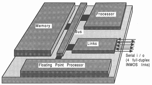
The INMOS transputer consists of a high-performance processor, on-chip RAM, and inter-processor communication links, all on a single chip of silicon. Figure 1 shows an example of the transputer family, the IMS T800 transputer.
The IMS T800 integrates a 32-bit micro-processor, a 64-bit floating point unit, four standard 20 Mbits/sec transputer communications links, 4 Kbytes of on-chip RAM, a memory interface and peripheral interfacing on a single CMOS chip. The floating point unit performs floating point operations concurrently with the CPU, and operates on single and double length (32 bit and 64 bit) items to the ANSI/IEEE 754-1985 floating point arithmetic standard. The concurrent operation allows floating point computation and address calculation to fully overlap, giving a realistically achievable performance of 1.5 MFLOPS (4 million Whetstones/second) on the 20 MHz part [5].
The on-chip RAM is part of the transputer’s address space, and allows critical routines and data to be accessed in a single machine cycle. The on-chip RAM can be thought of as replacing the register set found on conventional micro processors. The inter-processor links are controlled by autonomous DMA engines, and permit any number of transputers to be connected together in arbitrary networks, allowing extra processing power to be injected into a system very easily. The external memory interface allows linear access to a total memory space of 4 gigabytes.
Transputers can be programmed in conventional sequential languages such as C, Pascal, and FORTRAN. The occam language is supported to allow the development of complex parallel programs across multiple transputers. However, sequential sections of code written in C, Pascal or FORTRAN can be included in an occam program.
For further information on the transputer family, the reader is directed to [1].
The T800 is especially relevant in connection with SPICE, because of it’s floating point performance and the ability to interface to large amounts of external memory.
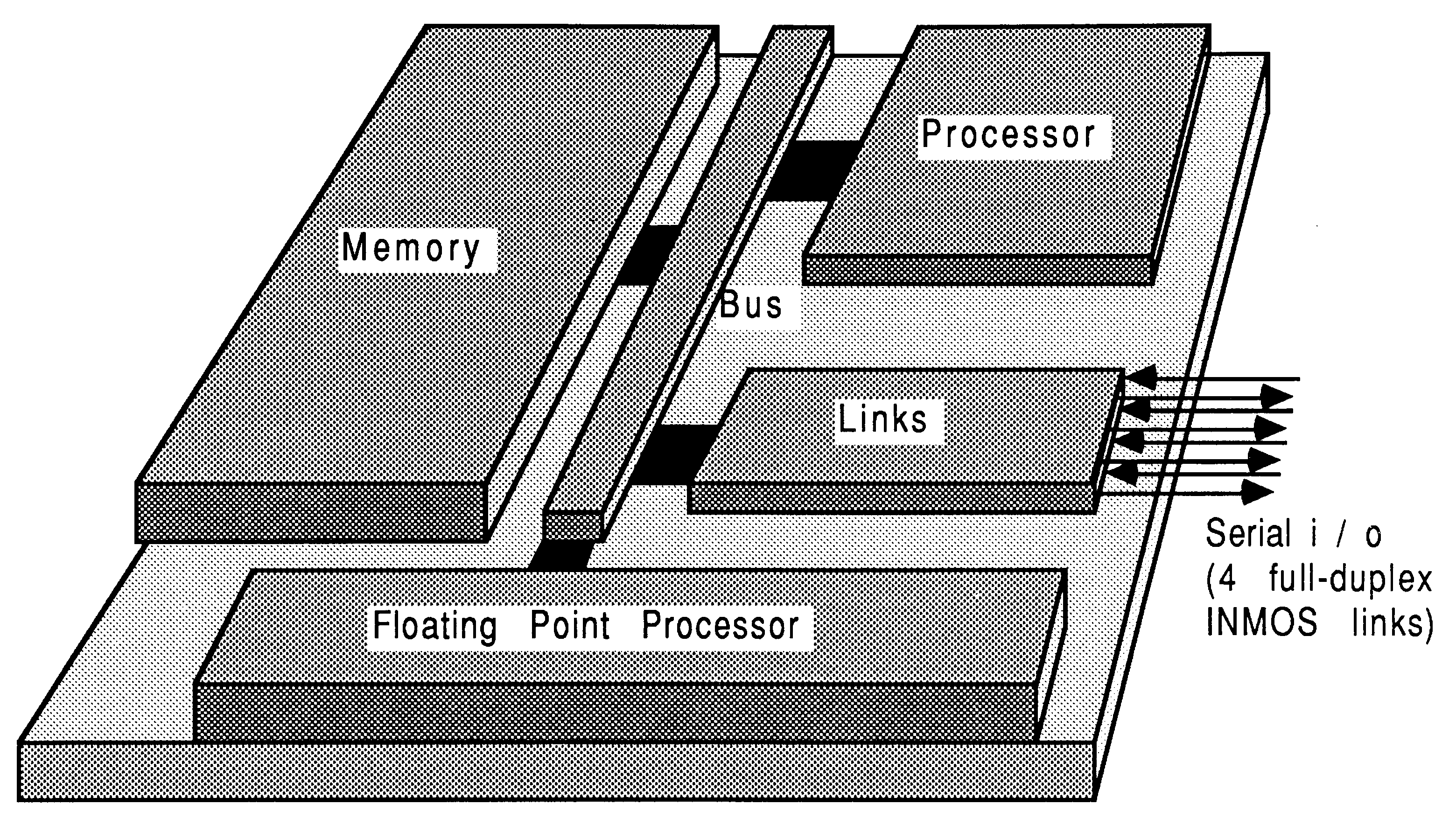
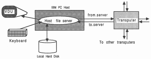
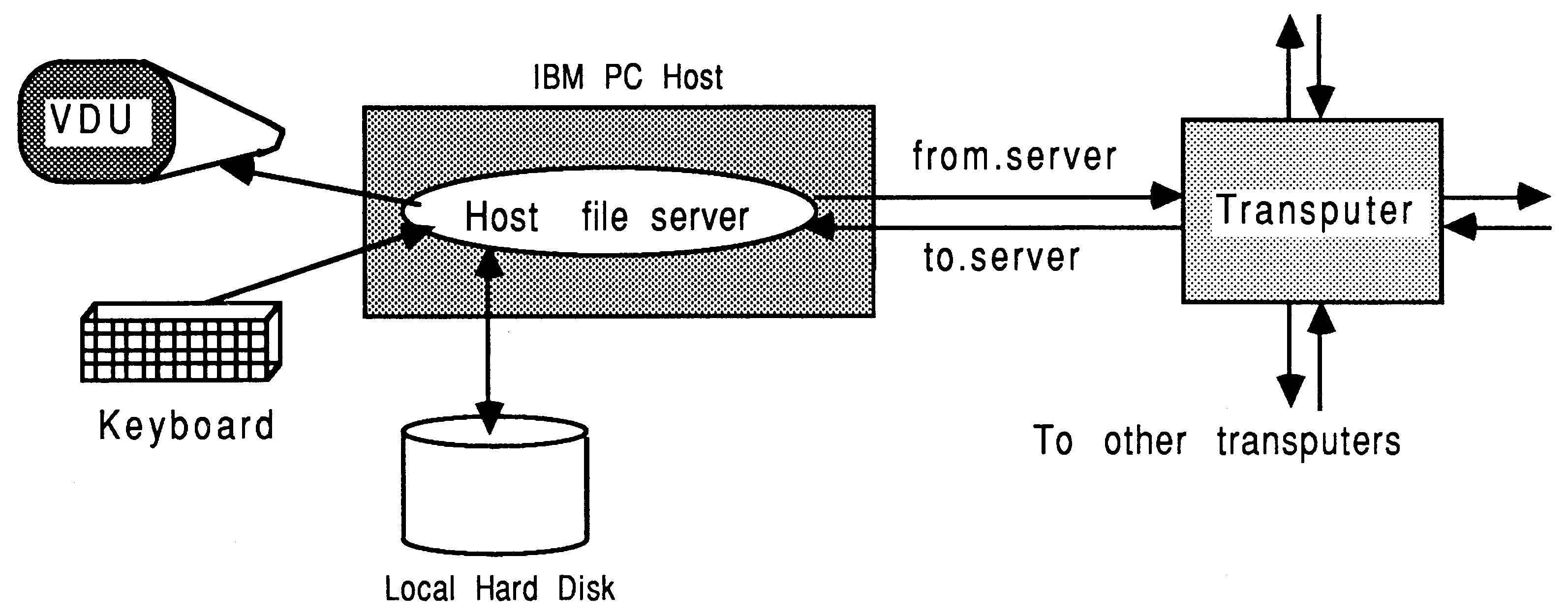
The transputer is normally employed as an addition to an existing computer, referred to as the host. Through the host, the transputer application can receive the services of a file store, a screen, and a keyboard. Presently, the host computer can be an IBM PC or compatible, a NEC PC, a DEC MicroVAX II, or a Sun-3. Also available are software tools to allow VAX development for transputer systems. For a more thorough guide to product availability, please refer to [6].
The transputer communicates with the host down a single INMOS link. A program, called a server, executes on the host at the same time as the program on the transputer network is run. All communications between the application running on the transputer and the host services (like screen, keyboard, and filing resources) take the form of messages, which are always initiated by the transputer system.
The transputer connected to the host by means of a link adapter is known as the root transputer. Figure 2 shows the root transputer of a transputer network. All other transputers in the network (if there are any) are connected, using INMOS links, to the root transputer.
A single process, such as SPICE, is run on a single transputer in the same way that a single process would be run on any other microprocessor. Using the development tools, the single conventional program is actually run as a process within a standard harness, which is used to establish the correct workspaces and provide access to the screen, keyboard, and filing facilities on the host. The communication channels defined in the harness are then mapped directly onto the hardware links of the transputer, allowing the application to execute.
Using the tools supplied with the transputer FORTRAN compiler, it is possible to sub-divide a single conventional program into a set of occam [7] processes. The occam mufti-process model for transputers is defined by the CSP model of communicating processes [8]. A system can be described in terms of a collection of concurrent processes which communicate with each other and with the outside world. Processes are connected together using synchronized, un-buffered, point-to-point, uni-directional communication channels. An example of this is shown in Figure 3, where each circle represents a process, and each arrow represents a communications channel. At this stage, there is no implied or rigidly defined mapping between the software processes and the actual hardware.
Some ways in which conventional programs such as SPICE can be distributed across a number of transputers are discussed in later sections of this document. The concepts of CSP and occam are only required to distribute multiple processes onto one or more processors. Note that there is no need to be familiar with occam in order to be able to directly port any conventional program, such as SPICE, to a single transputer.
SPICE is written in FORTRAN-77. The transputer FORTRAN compiler is based on the ANSI FORTRAN-77 standard, as defined in ANSI X3.9-1978. Extensions to the language have been provided as a transition aid from other FORTRAN dialects. A full description of this compiler can be found in [9].
The T800 transputer has 4 Kbytes of single-cycle on-chip RAM (50ns access time on a 20 MHz part). The on-chip RAM is usually at least four times faster than the external memory provided with most transputer boards. The fastest external memory supported by the transputer is three-cycle, with most boards using four or five-cycle memory, although using external RAM will not make programs run three to five times slower.
The next two sections describe how the FORTRAN compiler allows the on-chip RAM to be used, in terms of stack and code storage. The discussions are appropriate to any of the INMOS scientific language compilers.
The user can select to place the run-time stack either in on-chip RAM or in external memory.
If the whole of the stack for a program can be accommodated within 2 Kbytes, then it can be placed on-chip on either the T414 or the T800. The general heap storage is then placed in external memory. This is the default assumed by the standard occam harness.
If the size of the stack is expected to be larger than 2 Kbytes, then it must be placed off-chip, and the application is therefore run with all workspace off-chip. This is the manner in which SPICE is run. The parameter -:o 1, supplied to the host server at run-time, specifies that all workspace is to go off-chip. Note that no action is required at compile-time to specify the location of the stack. This facility should be used while developing a program, for which one is uncertain of the requirements in terms of stack size
The other half of on-chip RAM on the T800 (2 Kbytes) is reserved for code storage. The ordering of the files to link is critical for the performance of the program, because code placement on a processor is determined by the linking order of the binary object files. On the T800, files specified at the beginning of the link operation will be loaded into the 2 Kbytes of on-chip RAM that is not reserved for the variable stack. Programs will therefore run faster if small, speed-critical routines are placed at the beginning of the list of files to be linked, and the occam harness is placed at the end.
It is not possible to have the whole of on-chip memory on the T800 exclusively as a stack or code area. It is also not possible to have part of the stack on-chip and part of it off-chip. This is due to the implementation of the development tools. Note that on the T414, there is no internal RAM available for code storage with the scientific language compilers.
These restrictions on the specification of the scientific-language compilers were adopted for the following reasons. Studies showed that in the event of a trade-off in the use of on-chip memory between code and data, it is generally more efficient to permit some data to be placed on-chip (in the stack) rather than only having application code on-chip. This is due to the high density of transputer machine code, and the transputer’s hardware instruction pre-fetch mechanism. Therefore, to provide a development system that could be used on both the T800 and the T414 transputer, both transputers can have their internal RAM used as a variable stack (2 Kbytes in each case), but only the T800 can additionally accommodate some code.
Besides deciding whether to place the stack on or off-chip, the user can choose to place the local scalar variables of active subroutines on the heap or on the stack. Placing them on the heap guarantees that their values remain unchanged between calls to the same subroutines, but at a cost of a measured 20% performance penalty for the SPICE application.
By default, local scalar variables are placed on the stack. They are placed on the heap by using the /S compiler option. To the authors’ knowledge, SPICE does not rely on local variables retaining their values between subroutine calls, so they were placed on the stack.
In addition to local variables, the stack space of FORTRAN programs is also used for SUBROUTINE calls (5 words per level of calling), storing arguments, and run-time library workspace (about 40 words).
This chapter describes how to port SPICE to run on a single T800 transputer. Details of how to run compilers, linkers, and other software tools are not included, as these are readily available in the appropriate software documentation, and in [10].
There are around 130 source routines in SPICE, which fall into four categories with respect to porting to the transputer:
The following routines require no modification for use with the V1.1 transputer FORTRAN compiler:
ALFNUM ALIAS AVLM16 AVLM4
AVLM8 CHIVE CLRMEM CMEYER CMULT COMPRS CRUNCH DMPMEM ERRMEM EVTERM EXTMEM FETLIM GETCJE GETLIN GETM16 GETM4 GETM8 GETMX KEYSRC LIMVDS MAGPHS MEMADJ MEMORY MEMPTR MOSEQ1 MOSEQ2 MOSEQ3 MOSQ2 MOSQ3 MQSPOF NXTCHR NXTEVN NXTMEM NXTPWR PNJLIM PTRMEM RELMEM SCALE SLPMEM SIZMEM SHLSRT UNDEFI XXOR |
In porting SPICE to any new machine it is necessary to choose a value for the size of the COMMON array called VALUE, which is used to manage the dynamic data requirements of the program. On machines that support virtual memory it is usual to set this to a very large size, and leave the memory management system to page the data in and out of memory. However, the transputer does not support virtual memory, but a range of transputer boards are available with different physical memory sizes. It is therefore convenient to be able to easily change the size of VALUE in all the routines that reference it.
This would be most easily achieved by using an include mechanism, but unfortunately version V1.1 of the transputer FORTRAN compiler does not support included files. We used a simple DCL procedure and the EDT editor on the VAX to overcome this problem and to automate these changes in a single batch file, involving a search and replace operation for each of the listed files.
From the point of view of porting SPICE the following line:
COMMON /BLANK/ VALUE(......)
|
must be edited so that the array VALUE has a size suitable for the hardware to be used. For example, for a 2 Mbyte board, the array would consist of 150000 elements each of 8 bytes, which therefore occupies 1200 Kbytes of store. See section 5.5 for guidance in the calculation of appropriate sizes for this array.
Here are the routines requiring this treatment:
ACAN ACASOL ACDCMP ACLOAD
ACSOL ADDELT1 ADDNAM1 ALTER ASOL BJT CARD CODGEN COMCOF CPYTB4 CPYTB8 DCDCMP DCOP DCSOL DCTRAN1 DINIT DIODE DISTO DMPMAT ELPRNT1 ERRCHK EVPOLY EXTNAM FIND1 FNDNAM FOURAN GETNOD1 INDXX INTGR8 ITER8 JFET LNKREF LOAD MATLOC MATPTR MODCHK MOSCAP MOSFET NAMTAB1 NEWNOD1 NLCSRC NODSTR1 NOISE NTRPL8 OUTDEF1 OUTNAM1 OVTPVT PLOT PUTNOD1 READIN1 REORDR RESERV ROOT1 RUNCON1 SENCAL SETMEM SETPLT SETPRN SETUP SORSTP SORUPD1 SSTF SUBCKT SUBNAM SWAPIJ TERR TITLE1 TMPUPD TOPCHK1 TRUNC UPDATE |
The following routines are often supplied in assembler. Equivalent FORTRAN routines are given in section A, and we have compiled these to obtain the performance information given in this document.
COPY16 COPY4 COPY8
ZERO16 ZERO4 ZERO8 MOVE |
The block move instructions of the transputer could be used to write efficient assembler routine equivalents - refer to section D for some suggestions.
The following routines require modification, either due to machine dependency, unsupported language extensions, or compiler limitations
int loc(a)
int *a; { asm { ldl 2; /* return first parameter, which is */ /* the address of the parameter (a) */ } } |
This is compiled using the transputer C compiler2. The source must be compiled separately for the T414 and the T800 transputers to satisfy the processor type requirements imposed by the linker. The compiled code produced is compatible with that from the FORTRAN compiler, and is linked without problem. This is because the INMOS scientific language compiler set permits different parts of the same task (process) to be written in different languages, and to interact using the normal mechanisms of procedure / function calling.
It is also possible to write mufti-process, mixed-language applications (like the ones described in [10]), in which each process is written in one of the supported scientific languages. These processes then communicate with each other using occam channels.
The FORTRAN VALUE array, mentioned previously, occupies the largest amount of workspace in SPICE. The larger this array, the bigger the simulations that can be run. The size of this array is set to occupy about 300 Kbytes less than the amount of memory available on the board once the SPICE code has been loaded.
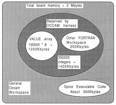
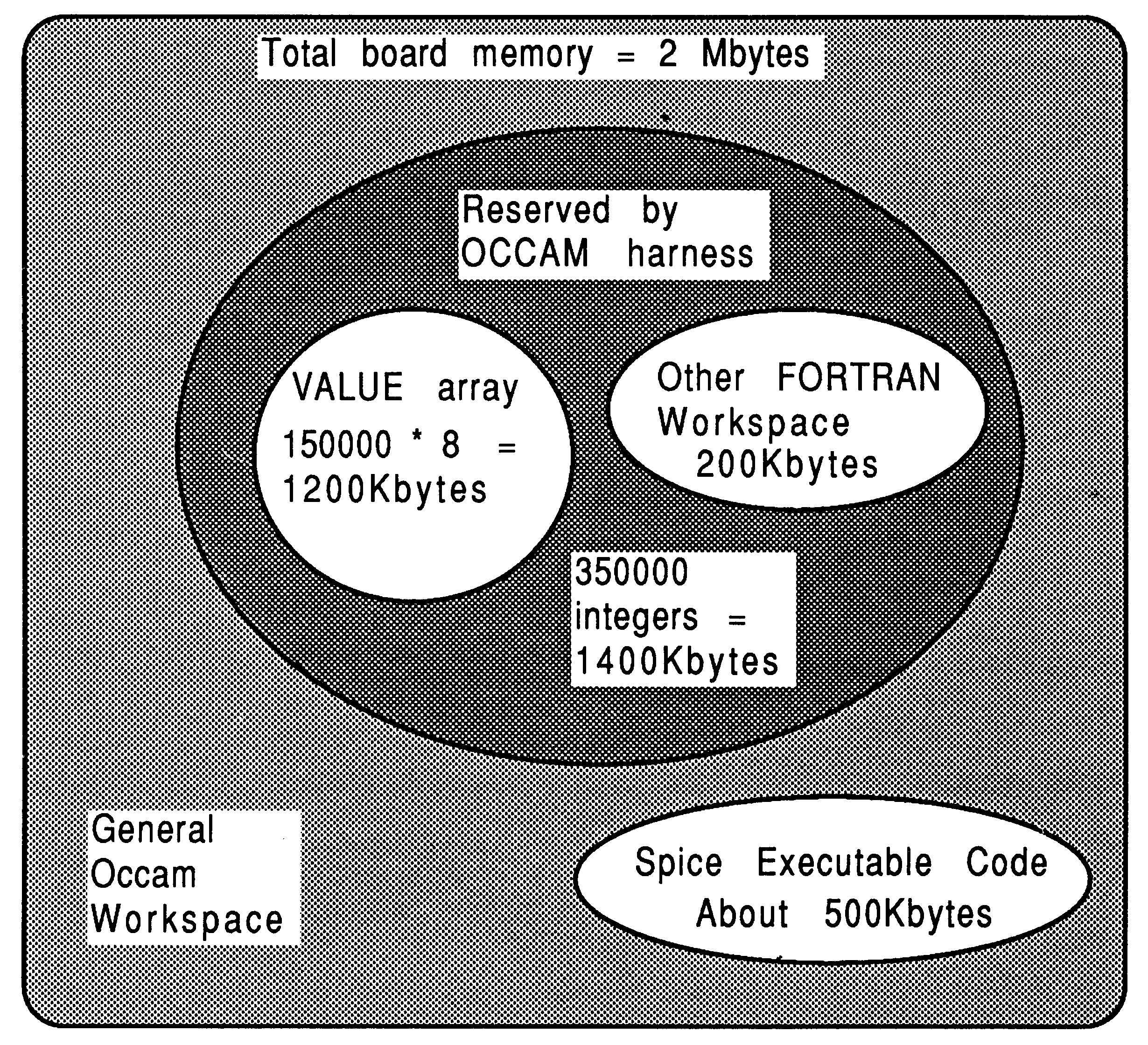
For example, an executable SPICE file takes about 500 Kbytes of memory, leaving 1500 Kbytes on a 2 Mbyte board (such as an IMS B004 with T800 [6]). Each element of the VALUE array occupies 8 bytes, so if the array was sized at 150000 elements, this would occupy 1200 Kbytes of store. So, the FORTRAN sources would all have the array dimensioned as 150000:
COMMON /BLANK/ VALUE(150000)
|
This is illustrated in Figure 4. The T800 internal on-chip RAM and the first 500 Kbytes are used for the SPICE executable code. The VALUE array occupies the next 1200 Kbytes of memory, with some additional FORTRAN workspace shown. The standard occam harness will automatically reserve sufficient workspace for SPICE, but if the user is intent on writing their own harness, then at least 1400 Kbytes of workspace must be reserved for SPICE. If an application has insufficient workspace, it will fail to operate.
As another example, on an IMS B405 TRAM board (8 Mbytes of RAM and a T800 transputer [6]), there is 7500 Kbytes of store available after SPICE has loaded. An array of 900000 floating point values occupies 7200 Kbytes of store (8 bytes per element). Therefore, the FORTRAN source code would have the array dimensioned at 900000:
COMMON /BLANK/ VALUE(900000)
|
SPICE uses the array VALUE to store all of its simulation data structures, and to store all the simulation output during simulation. This means that large amounts of data can be accumulated during a simulation and this is normally coped with by virtual memory. The requested user output is transferred to the output file at the end of the simulation.
This can give problems for large circuits on machines not supporting virtual memory, where little space is left in which to store simulation results.
The problem can be solved by making changes to the routine DCTRAN, to cause the required voltages and currents to be dumped to a file rather than to the array VALUE. These changes require a detailed understanding of the internal operation of SPICE, and are beyond the scope of this document.
The following table gives an indication of the performance of some randomly selected SPICE input decks when run on a variety of different machines. The first benchmark involves a simple resistor network, the second simulates an inverter circuit. The third benchmark represents a clock distribution network, and the fourth is a sense amplifier circuit. Comparisons were made between a Sun-3 (with and without a 68881 numeric co-processor), a VAX 11/785 with FPA3, and the T800 transputer.
The timings were obtained by averaging the time taken for the same job to be run several times on each machine in an attempt to isolate non-computational factors such as fluctuations in speed of disk access, I/O bandwidth, and CPU loading peaks. Note that the output files from all machines were identical. The timings represent the actual CPU times used, and are given in seconds.
| Machine | Resist | Invert | Corclk | SenseAmp |
| Sun-3/160C | 0.20 | 19.40 | 356.90 | 1855.50 |
| Sun-3+68881 | 0.30 | 4.60 | 44.20 | 266.70 |
| VAX 11/785+FPA | 0.38 | 4.51 | 30.22 | 141.55 |
| IMS T800-20 | 1.48 | 5.17 | 23.72 | 153.04 |
The transputer timings do not include the time taken to boot the transputer with SPICE - they are pure execution times. The boot time for SPICE is around 15 seconds, depending on the host computer, but once booted it can rerun instantly without any re-load penalties.
The high usage of floating point arithmetic in SPICE lends itself much better to the T800 transputer than the T414. The T414 requires almost 75 Kbytes of floating point software support, and SPICE ran about ten times slower than the T800 on the same jobs. Even without a floating point processor, the T414 is still faster than a Sun-3 without a floating point processor.
Note that for extremely small simulations, the simulation time on the transputer is dominated by file transfer times from the host PC.
The performance described in the previous section is typical of that which can be achieved using near-standard INMOS products. However, it is possible to obtain higher performance using the following techniques
Faster memory and shorter cycle times
The figures quoted above are for a T800-20 transputer with a 4-cycle memory interface. This compares with the IMS B004 evaluation board which is supplied with a T414 and a 5-cycle memory interface. The transputer can support a 3-cycle memory interface, which would reduce the run-times quoted above by an order of 25%.
Sample T800-25 components are now available, and using these with a shorter memory cycle time would increase performance by a father 25%.
Optimum linkage strategy
To make best use of the existing hardware without modifying the application code, software tools can be used to ensure optimal utilization of the T800’s on-chip RAM.
Code placement is determined by the linking order of the binary object files per processor. On the T800, files specified at the beginning of the link operation will be loaded into the 2 Kbytes of on-chip RAM that is not used for the variable stack. Programs will therefore run faster if small, speed-critical routines are placed at the beginning of the link list, and the harness is placed at the end. One can use profiling techniques4 to establish the routines which consume most CPU time, and place these in on-chip RAM.
Rewriting critical routines in assembler
As mentioned earlier, the SPICE routines to move, copy, and initialize blocks of memory are often ceded in assembler. The T800 has special instructions for performing block operations of this type. By encoding the move, copy and zero subroutine sets into C and then transputer assembler (to ensure the use of specific transputer instructions), a 5% to 10% performance increase was observed. This is shown in more detail in section D
Program profiling can also be used to establish the relative benefits in converting specific routines into C or transputer assembler code.
The work described so far in this technical note has demonstrated that a single transputer is a powerful processor in its own right. However, the transputer was specifically designed to allow many of them to be used to solve a single problem.
There are two ways in which multiple transputers can be applied to SPICE. The first is to increase the performance of SPICE by modifying the program to run parts of it across multiple transputers. The second is to increase the throughput of a series of SPICE tasks by means of a processor farm, in which many copies of SPICE are run simultaneously, each on its own transputer.
There are two compute intensive tasks performed by SPICE in a simulation. The first is to set up a matrix to be solved, which involves calculating the current through every element in the circuit from the model equations for the device. The second is to solve the matrix to obtain an improved estimate of the unknown voltages and currents in the circuit. Both of these operations have to be performed many times at each timestep in the simulation, and there are usually thousands of timesteps in each simulation.
For relatively small circuits, of less than around 100 nodes, the model evaluation dominates the simulation time. For larger circuits the matrix evaluation dominates, because the solution of large sparse matrices takes time of order O(n1.2) to O(n1.4), where n is the number of nodes in the circuit.
The distribution of the solution of matrix equations across multiple processors is currently a subject of much research [11, 12, 13]. It appears that by using the latency present in most large circuits, and by applying relaxation and partitioning techniques, it is possible to achieve significant performance increases by using multiple processors to solve large circuit simulation problems.
In the remainder of this section we discuss a simple technique which can be applied to SPICE to allow many transputers to be used to speed up the evaluation of the device models. This approach has already been experimentally applied to INMOS’s in-house circuit simulator.
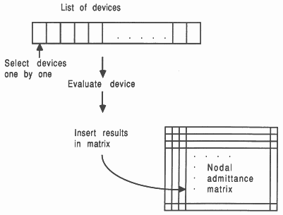
SPICE maintains a list of the devices whose currents have to be evaluated, as shown in Figure 5.
For each device its terminal voltages are passed as parameters to a routine which evaluates the current through the device (together with terminal to terminal capacitances and current derivatives with respect to terminal voltages). The calculated values are used to fill in the appropriate locations in the nodal admittance matrix. When this has been completed for all devices, the matrix is solved to obtain the next estimate of the node voltages in the circuit.
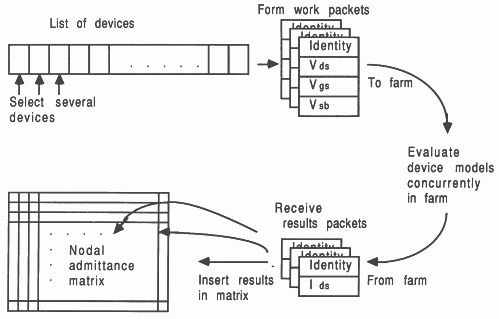
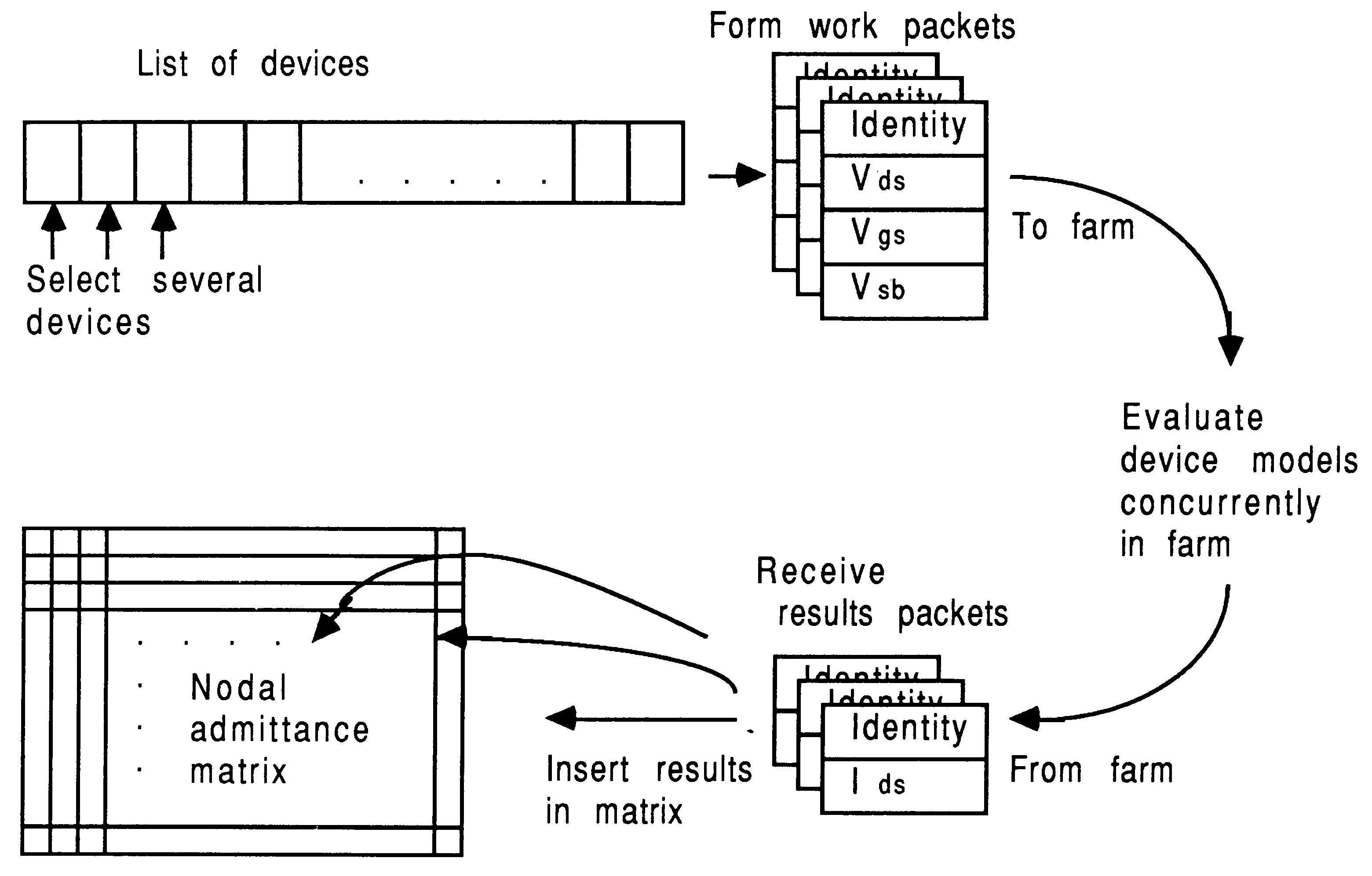
From the point of view of the present discussion it is important to notice that all the model evaluations are completely independent of each other. It does not matter in which order they are performed, or even if they are performed in parallel on separate machines!
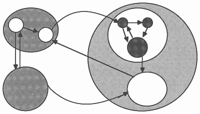
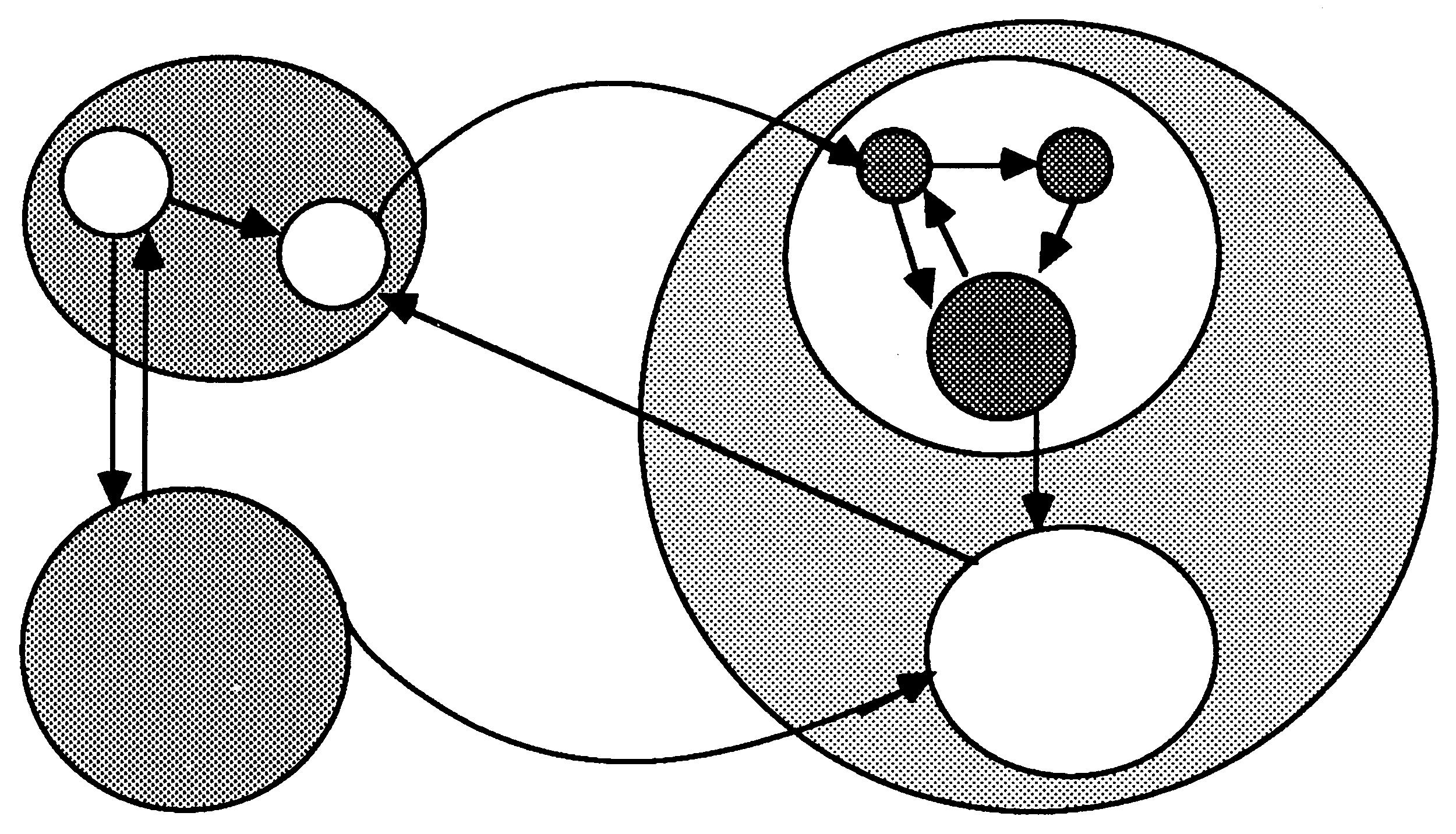
This fact can be used to distribute the model evaluations across a number of processors. Figure 6 shows how the concurrent model evaluations are handled, with respect to data movements in the system, by forming work packets for a farm of model evaluators. This figure can be usefully compared with Figure 5 shown previously.
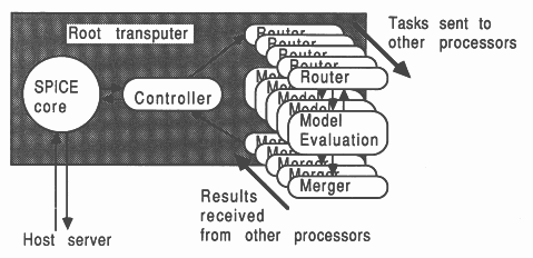
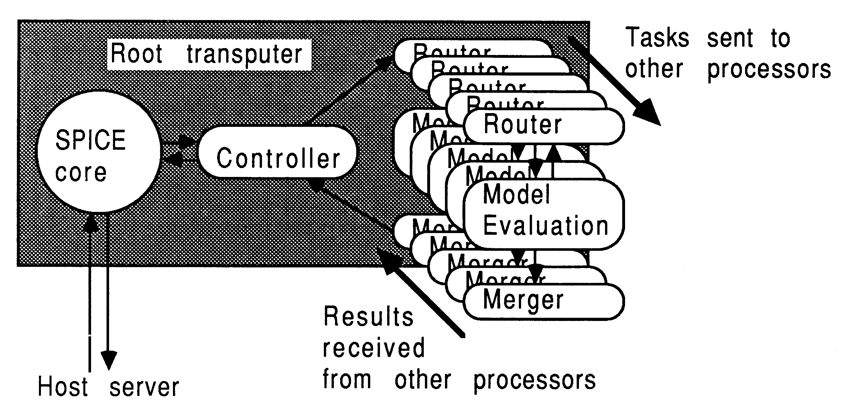
In hardware terms, one method of implementing this mechanism on a number of transputers is shown in Figure 7.
The core of SPICE is run on a single transputer, and the model evaluation routines are placed on a number of other transputers. SPICE is modified so that for each device to be evaluated it sends a message to the farm of model evaluation processors, specifying which device is to be evaluated and what its terminal voltages are. A free processor will accept the message, evaluate the model equations, and pass back a message containing the required results to the core transputer.
However, the core transputer is programmed so that it does not wait for this message to return, but continues to transmit requests for other devices to be evaluated. When a results message arrives back at the core processor it inserts the results in the appropriate location in the nodal admittance matins as before. Again, once all devices have been evaluated the single central transputer must solve the matrix, and the model evaluation processors will be idle during this period.
For small circuits of less than 100 nodes the model evaluations typically take 75% of the simulation time [14]. Therefore, halving the time taken for model evaluations by adding two extra transputers, should theoretically make the simulation run 38% faster. However, in practice another copy of the model evaluation process would be run on the core transputer, which would, at best, allow the model evaluation time to be reduced by a factor of three. Therefore we would expect to roughly halve the simulation time by using three transputers instead of one. From a circuit designers point of view this is a very worthwhile improvement.
Note that using an infinite number of transputers just to solve the model equations can at best only cut the simulation time by a factor of 4, as all the remainder to the simulation is still running on the single core machine. This illustrates that it is important to identify those sections of the code where parallelism is available, and to concentrate on applying the correct number of processors to exploiting this potential parallelism, without getting to the point that the remaining sequential sections of code completely dominate the CPU time.
Farming is a technique which can be applied to almost all existing applications, where the same program is run on a farm of processors, each one working on an independent set of data.
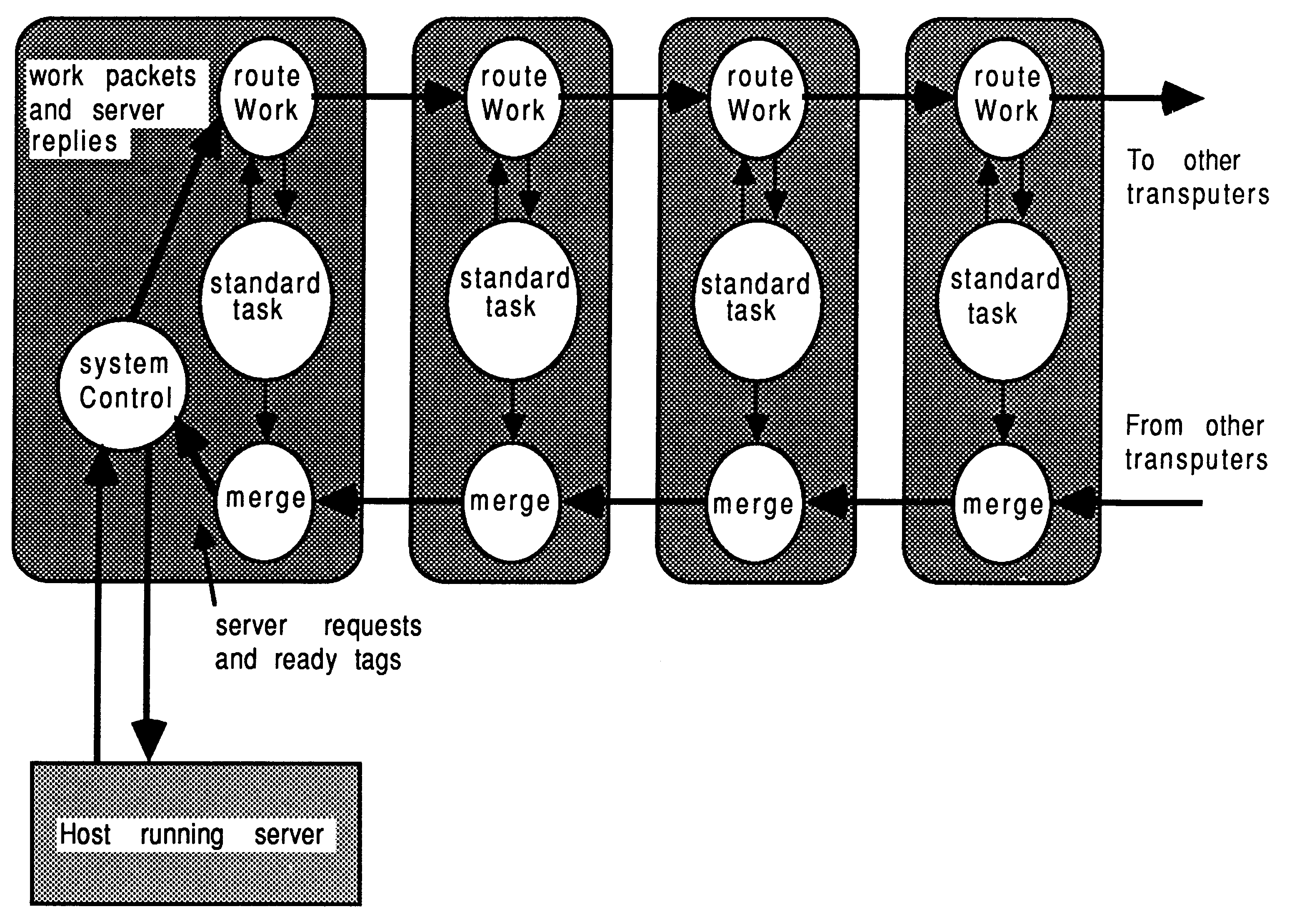
Some additional processes, usually written in occam are used to control and regulate the distribution of work within the farm. The techniques of farming are explained more fully elsewhere [15, 16, 17, 18, 2], though the general composition of a processor farm is shown below in figure 8.
Concurrent processes handle the tasks of work distribution, results collection, and performing the program itself. A system control process on the root transputer acts as an overall manager. Referring to Figure 8, the farm is controlled by the systemControl process, work is routed into the farm by the routeWork process, and results are collected by the merge process. In this case, the SPICE application is inserted in the place of the standardTask process.
Although the diagram shows a pipeline farm, the farm can have any connected topology. A pipeline is particularly easy to implement on the INMOS TRAM motherboards [6], as a suitable pipe is hard-wired into the motherboard, and requires no additional hardware or software configuration.
The list of tasks to be executed by the farm is made available to the systemControl process, and the transputers are fed with tasks until there are no more left. We used a small file on the host computer to specify the tasks to be performed. Although this approach operates several identical concurrent SPICE applications, the time taken by any given SPICE job is not reduced.
It would be possible to combine the techniques of this and the previous section, to arrive at a system where each farm ’worker’ was itself a number of transputers. In this case, each farm worker still executes identical code to its’ neighbours, but this code is distributed over a number of transputers.
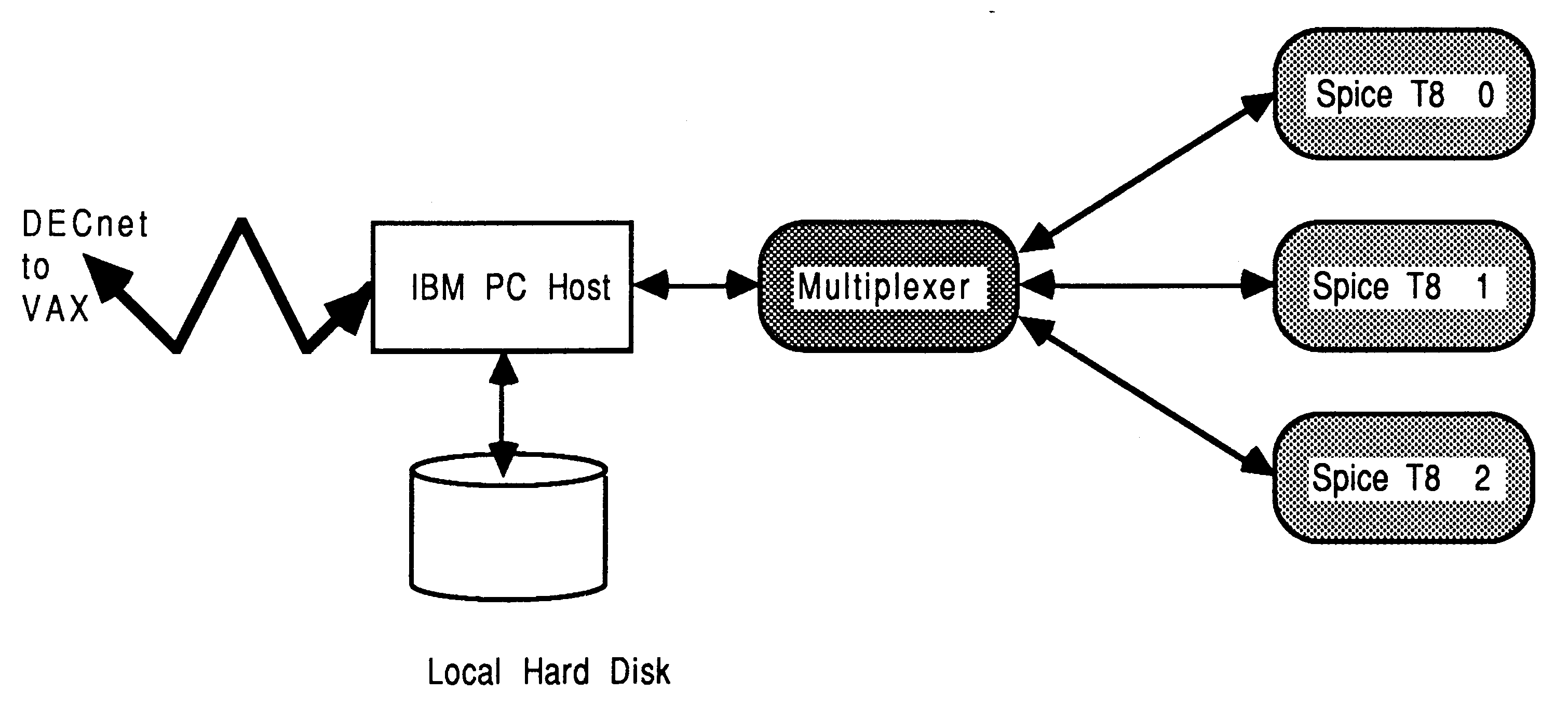
As an example of a SPICE farm, we have constructed a tree-like farm to relieve VAX CPU overhead, by offloading SPICE jobs from a VAX to a PC-hosted server which returns SPICE output files to the VAX. The server was written to communicate via DECnet, allowing the farm to become a remote processing engine for a VAX network. This is shown in Figure 9.
In this implementation, the PC server program was used to control the farm, receiving incoming task requests over DECnet. An occam multiplexes was used to correctly interleave SPICE accesses to the host facilities. Although a tree structure rather than a pipeline was used, the farming principle is the similar to that discussed in the previous section. A full discussion of our implementation of this DECnet-hosted farm server, as shown in Figure 9, can be found in [19].
This technical note has demonstrated that existing programs can be easily ported to run on the transputer. Very little modification was required to SPICE, which is a large and demanding application, to allow it to compile and run on the transputer.
The floating point performance of the IMS T800 allowed a pure FORTRAN version of SPICE to run more than one and a half times faster than on a Sun-3 with 68881 coprocessor, and nearly as fast as a version with assembler code routines running on a VAX 11/785 with floating point accelerator. By coding the same memory management routines in transputer assembler as those coded in assembler on the VAX, we obtained a performance equal to that of the VAX 11/785.
We have discussed how a single conventional program can be distributed over a number of processors, and illustrated some of the techniques that can be used to make use of potential parallelism in an application. We have also shown how a farm of transputers can be used as a cost effective way of offloading CPU intensive tasks from mainframe and mini-computers.
Acknowledgements
Glenn Hill and Vic Dewhurst of INMOS Bristol have made major contributions to this work.
This section lists the FORTRAN equivalents for the copy, zero, and move routines.
SUBROUTINE COPY4(IFROM,ITO,NWORDS)
IMPLICIT DOUBLE PRECISION (A-H,O-Z) C DIMENSION IFROM(1), ITO(1) C THIS ROUTINE COPIES A BLOCK OF #NWORDS# WORDS (OF THE C APPROPRIATE TYPE) FROM THE ARRAY #FROM# TO THE ARRAY #TO#. C IT DETERMINES FROM WHICH END OF THE BLOCK TO TRANSFER FIRST, C TO PREVENT OVER-STORES WHICH MIGHT OVER-WRITE THE DATA. C IF (NWORDS.EQ.0) RETURN IF (LOCF(IFROM(1)).LT.LOCF(ITO(1))) GO TO 20 C... LOCF() RETURNS AS ITS VALUE THE ADDRESS OF ITS ARGUMENT DO 10 I=1,NWORDS ITO(I)=IFROM(I) 10 CONTINUE RETURN C 20 CONTINUE DO 40 I=NWORDS,1,-1 ITO(I)=IFROM(I) 40 CONTINUE RETURN END SUBROUTINE COPY8 (RFROM, RTO, NWORDS) IMPLICIT DOUBLE PRECISION (A-H,O-Z) C DIMENSION RFROM(1),RTO(1) IF (NWORDS.EQ.0) RETURN IF (LOCF(RFROM(1)).LT.LOCF(RTO(1))) GO TO 120 DO 110 I=1,NWORDS RTO(I)=RFROM(I) 110 CONTINUE RETURN C 120 CONTINUE DO 140 I=NWORDS,1,-1 RTO(I)=RFROM(I) 140 CONTINUE RETURN END SUBROUTINE COPY16 (CFROM,CTO,NWORDS) IMPLICIT DOUBLE PRECISION (A-H,O-Z) C COMPLEX CFROM(1),CTO(1) IF (NWORDS.EQ.0) RETURN IF (LOCF(CFROM(1)).LT.LOCF(CTO(1))) GO TO 220 DO 210 I=1,NWORDS CTO(I)=CFROM(I) 210 CONTINUE RETURN C 220 CONTINUE DO 240 I=NWORDS,1,-1 CTO(I)=CFROM(I) 240 CONTINUE RETURN SUBROUTINE ZERO4(IARRAY,LENGTH) IMPLICIT DOUBLE PRECISION (A-H,O-Z) C DIMENSION IARRAY(1) C THIS ROUTINE ZEROES THE MEMORY LOCATIONS INDICATED BY C ARRAY (1) THROUGH ARRAY (LENGTH). C IF (LENGTH.EQ.0) RETURN DO 10 I=1,LENGTH IARRAY(I)=0 10 CONTINUE RETURN END SUBROUTINE ZERO8(ARRAY,LENGTH) IMPLICIT DOUBLE PRECISION (A-H,O-Z) C DIMENSION ARRAY(1) C THIS ROUTINE ZEROES THE MEMORY LOCATIONS INDICATED BY C ARRAY (1) THROUGH ARRAY (LENGTH). C IF (LENGTH.EQ.0) RETURN DO 10 I=1,LENGTH ARRAY(I)=0.ODO 10 CONTINUE RETURN END SUBROUTINE ZERO16(CARRAY,LENGTH) IMPLICIT DOUBLE PRECISION (A-H,O-Z) COMPLEX CARRAY(1) C C THIS ROUTINE ZEROES THE MEMORY LOCATIONS INDICATED BY C ARRAY (1) THROUGH ARRAY (LENGTH). C IF (LENGTH.EQ.0) RETURN DO 10 I=1,LENGTH CARRAY(I)=CMPLX(0.0E0,0.0E0) 10 CONTINUE RETURN END SUBROUTINE MOVE (A,I,B,J,N) CHARACTER*1 A(1),B(1) C C THIS ROUTINE MOVES N CHARACTERS FROM CHARACTER ARRAY B C TO CHARACTER ARRAY A, BEGINNING WITH THE J*TH AND I*TH C CHARACTER POSITIONS, RESPECTIVELY. C IF (N.EQ.0) RETURN DO 10 K=1,N A(I+K-1) =B(J+K-1) 10 CONTINUE RETURN END |
This section is concerned with changes made to ROOT to allow compilation with the V1.1 transputer FORTRAN compiler. The changes mostly concern the VAX-specific handling of files, dates, and times. The first part of each result shows the source as used on the VAX, and the second part shows the source as used on the transputer.
************
File [.VAX]ROOT.FOR;2 157 COMMON /VMSDAT/ BDATE 158 LOGICAL*1 BDATE(9) 159 CHARACTER*64 FILNAM 160 C File [.TX]ROOT.FOR;2 158 C COMMON /VMSDAT/ BDATE 159 C LOGICAL*1 BDATE(9) 160 C CHARACTER*64 FILNAM 161 C ************ File [.VAX]ROOT.FOR;2 169 C *************************************************** File [.TX]ROOT.FOR;2 170 DATA AHDRCMD / 8H00-00-00 / 171 C *************************************************** ************ File [.VAX]ROOT.FOR;2 185 CALL TODALF(ATIME) 186 CALL DATE(BDATE) 187 BOLTZ=1.3806226D-23 File [.TX]ROOT.FOR;2 187 C CALL TODALF(ATIME) 188 ATIME=AHDRCMD 189 C CALL DATE(BDATE) 190 BOLTZ=1.3806226D-23 ************ File [.VAX]ROOT.FOR;2 202 TYPE 1 203 1 FORMAT(’ INPUT FILE: ’$) 204 ACCEPT 2,FILNAM 205 2 FORMAT(A) 206 OPEN (UNIT=5,NAME=FILNAM,TYPE=’OLD’) 207 TYPE 3 208 3 FORMAT(’ OUTPUT FILE: ’$) 209 ACCEPT 2,FILNAM 210 OPEN (UNIT=6,NAME=FILNAM,TYPE=’NEW’) 211 C File [.TX]ROOT.FOR;2 205 C TYPE 1 206 C 1 FORMAT(’ INPUT FILE: ’$) 207 C ACCEPT 2,FILNAM 208 C 2 FORMAT(A) 209 C OPEN (UNIT=5,NANE FILNAM,TYPE=’OLD’) 210 C TYPE 3 211 C 3 FORMAT(’ OUTPUT FILE: ’$) 212 C ACCEPT 2,FILNAM 213 C OPEN (UNIT=6,NAME=FILNAM,TYPE=’NEW’) 214 OPEN (UNIT=5,FILE=’SPICE.IN’,STATUS=’OLD’) 215 OPEN (UNIT=6,FILE=’SPICE.OUT’,STATUS=’NEW’) 216 C ************ File [.VAX]ROOT.FOR;2 215 CALL TIMRB 216 CALL GETCJE File [.TX]ROOT.FOR;2 220 C CALL TIMRB !CMD 221 CALL GETCJE ************ File [.VAX]ROOT.FOR;2 354 CALL TIMRE 355 ET=TIME2-TIME1 File [.TX]ROOT.FOR;2 359 C CALL TIMRE !CMD 360 ET=TIME2-TIME1 ************ File [.VAX]ROOT.FOR;2 368 900 IF ((MAXTIM-ITIME).GE.LIMTIM) GO TO 10 369 WRITE (IOFILE,901) 370 901 FORMAT(’1WARNING: FURTHER ANALYSIS STOPPED DUE TO CPU TIME LIMIT’ 371 1/) 372 1000 IF(NODATA.NE.0) WRITE(IOFILE,1001) File [.TX]ROOT.FOR;2 373 C 900 IF ((MAXTIM-ITIME).GE.LIMTIM) GO TO 10 374 C WRITE (IOFILE,901) 375 C 901 FORMAT(’1WARNING: FURTHER ANALYSIS STOPPED DUE TO CPU TIME LIMIT’ 376 C 1/) 377 1000 IF(NODATA.NE.0) WRITE(IOFILE,1001) ************ |
This section is concerned with changes made to the TITLE routine to permit compilation with the V1.1 transputer FORTRAN compiler. The changes mostly concern the VAX-specific handling of dates and times. The first part of each result shows the source as used on the VAX, and the second part shows the source as used on the transputer.
************
File [.VAX]TITLE.FOR;2 33 COMMON /VMSDAT/ BDATE 34 LOGICAL*1 BDATE(9) 35 C File [.TX]TITLE.FOR;2 33 C COMMON /VMSDAT/ BDATE 34 C LOGICAL*1 BDATE(9) 35 C ************ File [.VAX]TITLE.FOR;2 47 WRITE (IOFILE,31) BDATE,APROG,ATIME,(ATITLE(I),I=1,10) 48 31 FORMAT(1H1,15(1H*),9A1,1X,23(1H*),3A8,23(1H*),A8,15(1H*)//1H0, 49 1 15A8/) File [.TX]TITLE.FOR;2 47 C WRITE (IOFILE,31) BDATE,APROG,ATIME,(ATITLE(I),I=1,10) 48 WRITE (IOFILE,31) APROG,ATIME,(ATITLE(I),I=1,10) 49 C 31 FORMAT(1H1,15(1H*),9A1,1X,23(1H*),3A8,23(1H*),A8,15(1H*)//1H0, 50 31 FORMAT(1H1,15(1B*),10(1H*),23(1H*),3A8,23(1H*),A8,15(1H*)//1H0, 51 1 15A8/) ************ File [.VAX]TITLE.FOR;2 58 100 WRITE (IOFILE,101) BDATE,APROG,ATIME,(ATITLE(I),I=1,10) 59 101 FORMAT(1H1,7(1H*),9A1,1X,7(1H*),3A8,7(1H*),A8,5(1H*)//1H0,10A8/) 60 IF (ICOM.EQ.0) GO TO 110 File [.TX]TITLE.FOR;2 60 C 100 WRITE (IOFILE,101) BDATE,APROG,ATIME,(ATITLE(I),I=1,10) 61 100 WRITE (IOFILE,101) APROG,ATIME,(ATITLE(I),I=1,10) 62 C 101 FORMAT(1H1,7(1H*),9A1,1X,7(1H*),3A8,7(1H*),A8,5(1H*)//1H0,10A8/) 63 101 FORMAT(1H1,7(1H*),10(1H*),7(1H*),3A8,7(1H*),A8,5(1H*)//1H0,10A8/) 64 IF (ICOM.EQ.0) GO TO 110 ************ |
As an example of re-writing a SPICE FORTRAN subroutine in transputer assembler, consider the move subroutine.
The FORTRAN for this routine has already been shown in section A. Since the transputer FORTRAN compiler does not permit the inclusion of transputer assembler mnemonics, the first stage is to code and test an equivalent routine written in C. This is shown below:
int move (a, i, b, j, n)
char *a, *b; int *i, *j, *n; { int k; if (*n == 0) return; for ( k=-1; k < (*n)-1; k ++) a[(*i)+k] = b[(*j)+k]; } |
A couple of points need explaining here. Firstly, the parameter passing mechanism implemented in the transputer FORTRAN compiler is to call by reference. Secondly, arrays in FORTRAN (in SPICE) generally start from subscript 1, and those in C start from subscript 0. This accounts for the start and finish values of the index variable k shown above.
The V1.3 transputer C compiler allows limited transputer assembler inserts, using the asm directive. So, the loop construct in the C representation is replaced by an explicit transputer assembler instruction, the move instruction. One way of doing this is shown below:
int move (a, i, b, j, n)
char *a, *b; int *i, *j, *n; { int source, dest, len; source = b + (*j) - 1; dest = a + (*i) - 1; len = *n; asm { ldl 0 ; /* source */ ldl 1 ; /* dest */ ldl 2 ; /* len */ move ; } } |
The move instruction is more fully described in [20], but briefly it takes a source, destination, and byte count, and performs a fast memory copy operation. The arguments are easily set up in C, and there is little performance penalty as this is only done once. The C compiler allocates local integer automatic variables in the order they are declared, starting from workspace location 0. Therefore, the instruction ldi 0 will access the data held in source, which is the address of the vector b.
By implementing the seven move, copy, and zero routines in C, a 5% to 7% performance increase over the FORTRAN equivalents were observed. This can partly be explained by remembering that the FORTRAN routines had to call C functions to obtain the addresses of the vectors being operated on this overhead is not incurred here. By implementing the move function in the assembler shown above, another 2% increase was observed.
This technique can also be used in other areas.
[1] Transputer Reference Manual, INMOS Limited, Prentice Hall.
[2] Issues in Application porting and farming, Technical Note 53, INMOS Limited.
[3] SPICE2: A computer program to simulate semiconductor circuits, L. W. Nagel, Memorandum No. ERL-M520, University of California, Berkeley. May, 1975
[4] Program Reference for SPICE2, E. Cohen, Memorandum No. ERL-M592, University of California, Berkeley. June, 1976
[5] Lies, damned lies, and benchmarks, Technical Note 27, INMOS Limited.
[6] INMOS Spectrum, (Contains a brief description of INMOS products) INMOS Limited.
[7] Occam 2 Reference Manual, INMOS Limited, Prentice Hall.
[8] Communicating Sequential Processes, C. A. R. Hoare, Prentice Hall 1985.
[9] 3L FORTRAN Reference Manual (compiler version 1.1), INMOS Limited
[10] Using the occam toolset, Technical Note 55, INMOS Limited.
[11] Relaxation techniques for the simulation of VLSI circuits, J. K. White and A. Sangiovanni-Vincentelli, Kluwer Academic Publishers, 1987
[12] A Pipelined Event-driven Mixed-mode Simulator, Clive M. Dyson and Alan H. Gray, IEEE Int. Conf on Computer-Aided Design, pp 488.491 Santa clara, California, 1987
[13] CINNAMON : Coupled integration and nodal analysis of MOS networks, L. M. Vidigal, S. R. Nassif and S. W. Director, 23rd Design Automation Conference, pp 179-198,1986
[14] The Simulation of Large-scale Integrated Circuits, A. Richard Newton, Memorandum No. ERL-M78-52, University of California, Berkeley. July, 1978
[15] Exploiting concurrency; A Ray tracing Example, Technical Note 7, INMOS Limited.
[16] Program design for concurrent systems, Technical Note 5, INMOS Limited.
[17] Performance Maximization, Technical Note 17, INMOS Limited.
[18] Communicating Process Computers, Technical Note 22, INMOS Limited.
[19] A transputer farm accelerator for networked computing facilities, Technical Note 54, INMOS Limited.
[20] Transputer instruction set: a compiler-writer’s guide, INMOS Limited, Prentice Hall