|
|
| Simpler real-time programming with the transputer _____________________________________________________________________ |
| Jamie Packer Central Applications Group INMOS Bristol May 1988 |
INMOS manufactures a range of high performance microprocessors, called transputers, which combine all the essential elements of a computer (processor, memory and i/o) in a single component. Transputers provide support, in hardware and microcode, for concurrency and communication. This support includes communication links for connecting transputers together and two hardware timers which can be used for interval measurement or for real-time scheduling.
The occam language was designed for programming systems composed of concurrently executing, communicating processes and, as such, is especially suitable for transputer based systems. An important application of modern microprocessor systems is real-time control and occam provides many features for this purpose. One of these is the timer, a means of measuring time periods and generating time delays.
This technical note describes some aspects of timers on the transputer, using occam. It introduces the basics of the occam language and then goes on to show some simple ways in which timers can be used in programs. The next section describes how the transputer implements timers. Finally there are some examples taken from occam programs which illustrate various aspects of the use of timers.
The occam language enables a system to be described as a collection of concurrent processes which communicate with one another, and with the outside world, via communication channels.
This section is a brief introduction to occam and, as such, can be skipped by those familiar with the language. Occam programs are built from three primitive processes:
| variable := expression | assign value of expression to variable |
| channel ? variable | input a value from channel to variable |
| channel ! expression | output the value of expression to channel |
Each occam channel provides a one way communication path between two concurrent processes. Communication is synchronised and unbuffered. The primitive processes can be combined to form constructs which are themselves processes and can be used as components of other constructs.
Conventional sequential programs can be expressed by combining processes with the sequential constructs SEQ, IF, CASE and WHILE. Concurrent programs are expressed using the parallel construct PAR, the alternative construct ALT and channel communication. PAR is used to run any number of processes in parallel and these can communicate with one another via communication channels. The alternative construct allows a process to wait for input from any number of input channels. Input is taken from the first of these channels to become ready and the associated process is executed.
Sequence
A sequential construct is represented by
SEQ
P1 P2 P3 ... |
The component processes P1, P2, P3 ... are executed one after another. Each component process starts after the previous one terminates and the construct terminates after the last component process terminates. For example
SEQ
c1 ? x x := x + 1 c2 ! x |
inputs a value, adds one to it, and then outputs the result.
Sequential constructs in occam are similar to programs written in conventional programming languages.
Parallel
A parallel construct is represented by
PAR
P1 P2 P3 ... |
The component processes P1, P2, P3 ... are executed together, and are called concurrent processes. The construct terminates after all of the component processes have terminated, for example:
PAR
c1 ? x c2 ! y |
allows the communications on channels c1 and c2 to take place together.
The parallel construct is unique to occam. It provides a straightforward way of writing programs which directly reflects the concurrency inherent in real systems. Concurrent processes communicate only by using channels, and communication is synchronized. If a channel is used for input in one process, and output in another, communication takes place when both the inputting and the outputting processes are ready. The value to be output is copied from the outputting process to the inputting process, and the processes then proceed.
Conditional
A conditional construct
IF
condition1 P1 condition2 P2 ... |
means that P1 is executed if condition1 is true, otherwise P2 is executed if condition2 is true, and so on. Only one of the processes is executed, and then the construct terminates, for example:
IF
x=0 y := y + 1 x<>0 SKIP |
increases y only if the value of x is 0.
Alternation
An alternative construct
ALT
input1 P1 input2 P2 input3 P3 ... |
waits until one of input1, input2, input3 ... is ready. If input1 first becomes ready, input1 is performed, and then process P1 is executed. Similarly, if input2 first becomes ready, input2 is performed, and then process P2 is executed. Only one of the inputs is performed, then its corresponding process is executed and then the construct terminates, for example:
ALT
count ? signal counter := counter + 1 total ? signal SEQ out ! counter counter := 0 |
either inputs a signal from the channel count, and increases the variable counter by 1, or alternatively inputs from the channel total, outputs the current value of the counter, then resets it to zero. The ALT construct provides a formal language method of handling external and internal events that must be handled by assembly level interrupt programming in conventional languages.
Loop
WHILE condition
P |
repeatedly executes the process P until the value of the condition is false, for example:
WHILE (x - 5) > 0
x := x - 5 |
leaves x holding the value of (x remainder 5) if x were positive.
Selection
A selection construct
CASE s
n P1 m,q P2 ... |
means that P1 is executed if s has the same value as n, otherwise P2 is executed if a has the same value as m or q, and so on, for example:
CASE direction
up x := x + 1 down x := x - 1 |
increases the value of x if direction is equal to up, otherwise if direction is equal to down the value of x is decreased.
Replication
A replicator is used with a SEQ, PAR, IF or ALT construction to replicate the component process a number of times. For example, a replicator can be used with SEQ to provide a conventional loop.
SEQ i = 0 FOR n
P |
causes the process P to be executed n times.
A replicator may be used with PAR to construct an array of concurrent processes.
PAR i = 0 FOR n
Pi |
constructs an array of n similar processes P0, P1, ..., Pn-1. The index i takes the values 0, 1, ..., n-1, in P0, P1, ..., Pn-1 respectively.
This note contains some short program examples written in occam. These should be readily understandable but, if necessary, a full definition of the occam language can be found in the occam reference manual [1].
This section gives more detail of the TIMER in occam.
An occam timer provides a clock which can be read to provide a value representing the time. The timer is read by an input statement similar to that used for receiving data from a channel. Unlike a communication channel, a single timer can be shared by any number of concurrent processes. Timers are declared in an occam program to be of type TIMER in the same way as channels and variables are declared. An example of the use of timers is shown below.
TIMER clock :
INT t : SEQ ... clock ? t -- read value of timer ‘clock’ into ‘t’ ... |
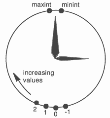
The value input from a timer is of type iNT. The value is derived from a clock which increments by a fixed amount at regular intervals. The value of the clock is cyclic, that is when the time reaches the most positive integer value then the next increment results in the most negative value. An analogy can be drawn here with a real clock. We normally understand whether a particular time is before or after another from the context.
For example 11 o’clock would normally be considered to be before 12 o’clock, and 12 o’clock to be before 1 o’clock. This comparison only works for limited ranges of times. For example we may consider 6 pm to be after 12 noon, but 7 am to be before noon (i.e. 7 am is before 6 pm even though 6 is less than 7).
A special operator, AFTER, can be used to compare times in occam. AFTER is one of a set of modulo operators, these perform arithmetic with no overflow checking and thus produce cyclic results. Two other modulo operators useful with timer values are PLUS and MINUS which perform addition and subtraction respectively. For example, if maxint is the largest value of type INT that can be represented, then maxint PLUS 1 wraps around and becomes the most negative representable integer (minint), this is illustrated in Figure 1. a AFTER b is defined to be equivalent to (b MINUS a) > 0. The value t2 AFTER t1 is true if the value of t2 represents a later time than the value of t1. This comparison is only valid for times within half a timer cycle of one another because (b MINUS a) must be positive.
The AFTER operator can also be used in a timer input to create a delayed input. This specifies a time after which the input terminates. For example:
TIMER clock :
SEQ ... clock ? AFTER t ... |
This example will wait until the value of the timer clock is later than the value of t.
This section outlines the basic applications of timers in occam programs.
Perhaps the most obvious use of a timer is for measuring time intervals. Different timers are not guaranteed to have the same value so time intervals must be measured using a single timer.
For example, when benchmarking programs written in occam, the timer can be read before and after executing the main body of the code:
TIMER clock :
INT t1, t2, time : SEQ clock ? t1 -- read start time into t1 ... run benchmark clock ? t2 -- read end time into t2 time := t2 MINUS t1 -- calculate elapsed time ... print time taken |
There are a few important points to note about this example.
The next application of timers is to use the delayed input to generate a known time delay. This is very simple as shown below:
TIMER clock :
INT now : VAL delay IS 1000 : -- delay time in clock ‘ticks’ SEQ clock ? now clock ? AFTER now PLUS delay |
This example reads the current value of the timer, then the delayed input waits until the value of the timer is later then the value of now PLUS delay. The process is descheduled while waiting so other processes can be executed. An important practical point here is that there may be a delay before the process is rescheduled. This latency may be due to a number of factors, e.g. the number of other processes executing at the time, and may be variable. The transputer implements process scheduling in hardware and so the latency can be very small (see Section 4.1).
Again, note the use of the modulo operator PLUS to calculate the time to wait until and the fact that the greatest delay is half the timer’s cycle time. A technique for generating delays of arbitrary length is given in in Section 5.5.
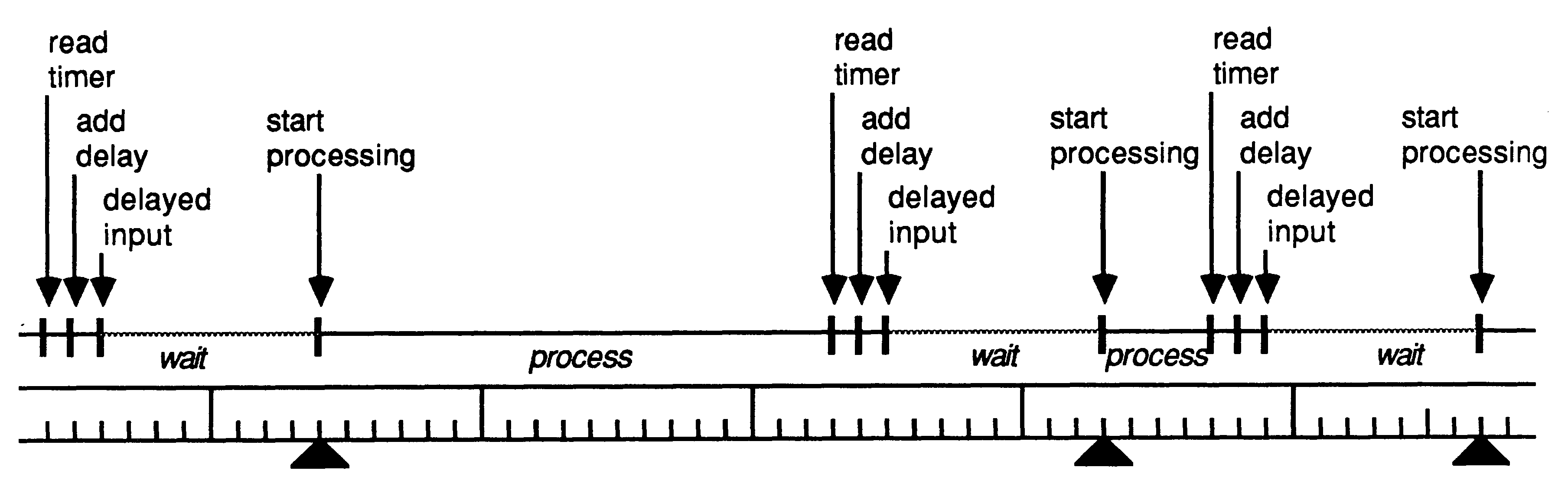
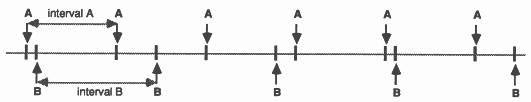
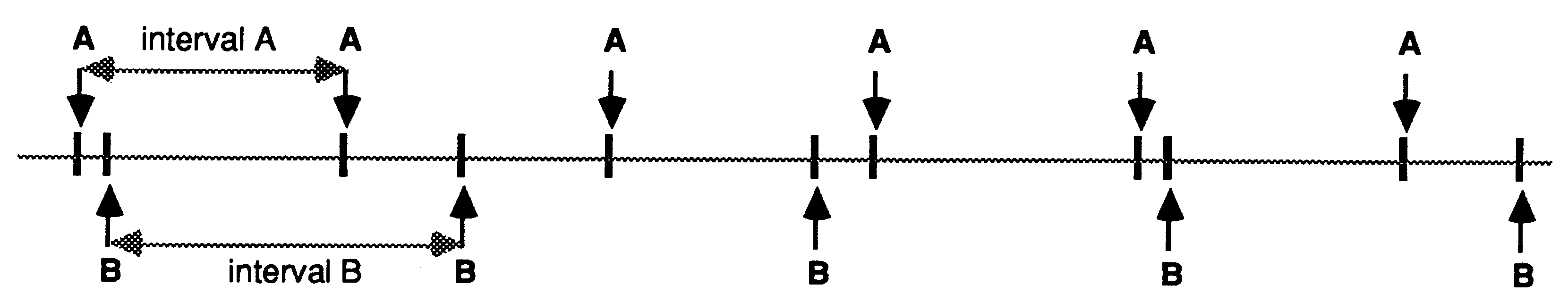
A program which must perform a task at regular intervals cannot do so simply by means of a fixed delay between processing, as in the previous example. If a simple delay were used then the time at which the task happens will slip gradually because the delay does not account for the time taken by the task itself (which may vary) and this error accumulates. This is illustrated in Figures 2 & 3.
To make this more explicit, assume the task must be scheduled every millisecond and will execute for 10μs. The task executes and is then descheduled for 1ms (plus the time required to reschedule the process). The interval between tasks is therefore at least 1.01 ms and this error will accumulate so, after 1 second the task will have been executed only 990 times instead of 1000 times. It would be possible to adjust the delay to take the processing time of the task into account, but this implies that the processing time is both known and fixed. This is unlikely to be the case in a real system. Consider the following example:
TIMER clock :
INT time : SEQ WHILE active SEQ ... perform process P at intervals -- wait for ‘delay’ clock ticks clock ? time clock ? AFTER time PLUS delay |
The time taken to execute the loop is the delay time plus the execution time of process P. Any variation in the processing required in P will vary the frequency at which it is executed.
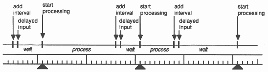
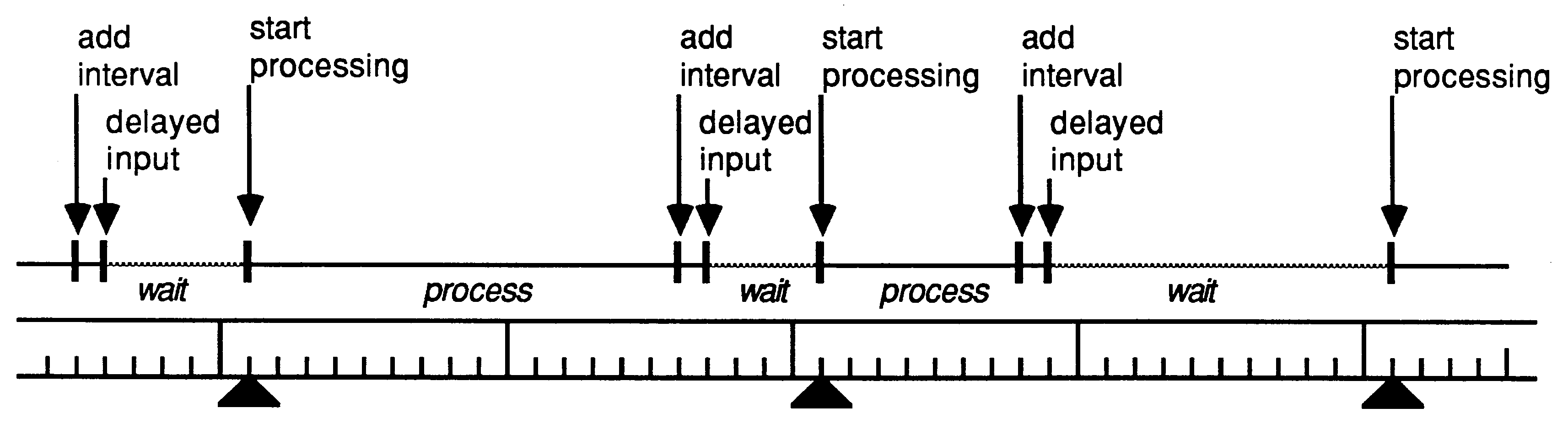
A far more accurate way to achieve the desired effect is shown below:
TIMER clock :
INT time : SEQ clock ? time WHILE active SEQ ... perform process P at regular intervals -- add interval to the time the process started time := time PLUS interval -- and wait until it is time to execute the process again clock ? AFTER time |
The important point to note here is that the value of the timer is only read once, before the loop is entered.
After that the time is updated by adding a constant increment to the current value. This ensures that the delayed input always waits until the desired starting time, rather than for a fixed delay. This prevents any drift in the timing of the processing.
To take the previous example of a task being scheduled every millisecond, it can be seen that the task is initiated at (or shortly after, because of scheduling latency) the time specified by the value of time. When the task has completed a constant amount is added to the value of time to calculate the time the task should next be scheduled. This time is independent of the time taken by the task. The possible variation in the time taken to schedule a process may introduce some jitter into the timing of the task, but will not cause it to slip.
Delayed timer inputs are often used in alternative constructs.
An alternative may be used to interleave processing at fixed times with processing performed when data is received. As an example, a data logging process may need to record data received from a channel and, at suitable intervals, insert a time stamp in the recorded data. This could be written with an ALT very simply:
TIMER clock :
INT time, data : SEQ clock ? time WHILE active SEQ time := time PLUS one.second PRI ALT clock ? AFTER time ... insert time stamp in file in ? data ... store data in file |
Note that the delayed input is prioritised with respect to the channel input; this ensures that, even if the channel in is always ready, the time stamping process will be selected when it becomes ready.
Another use of delayed inputs in alternatives is to provide some sort of timeout on channel communication. This may be to execute a process if no user command is received, or to detect an error condition. For example, a disk controller may wish to ’park’ the heads (i.e. move them to a safe position on the disk) if no commands are received within a time limit:
WHILE active
SEQ clock ? time ALT (headsNotParked) & clock ? AFTER time PLUS timeout ... move heads to shipping track in ? command ... execute command from file system |
An alternative may contain several delayed inputs with different delays. This may be useful if it is necessary to handle a number of devices at different, fixed intervals. For example, if the processor needs to be scheduled to service two peripherals at different periods then an ALT can be used to correctly interleave the handling of these devices:
TIMER clock :
INT timeA, timeB : VAL intervalA IS 96 : VAL intervalB IS 42 : SEQ clock ? timeA clock ? timeB WHILE active ALT clock ? AFTER timeA SEQ timeA := timeA PLUS intervalA ... handle device A at fixed intervals clock ? AFTER timeB SEQ timeB := timeB PLUS intervalB ... handle device B at fixed intervals |
Only times that are within half a timer cycle can be compared by AFTER so, if several times are being compared, they must all be within half a cycle of one another. If an ALT contains more than one delayed input then all of the times involved (including the present timer value) must be within half a cycle of one another. A simpler, but sometimes more restrictive, rule is to ensure that all times in the delayed inputs are within a quarter of a cycle of the current timer value.
The transputer [2] has hardware and microcode support for occam timers. This allows timer instructions to be fast and, more importantly, delayed inputs to be non-busy (i.e. to consume no processor time whilst waiting). There are two timer clocks, with the same wordlength as the particular device, which tick periodically. One timer is accessible only to high priority processes and is incremented every microsecond. The other can only be accessed by low priority processes and ticks every 64 μs, giving exactly 15,625 ticks per second. The cycle time of these timers depends on the wordlength of the device. The approximate cycle times, for the current range of 16 and 32 bit transputers, are shown in the table below.
| Transputer type | Priority
| |
| High | Low | |
| IMS T800 & IMS T414 | 1.2 hours | 76 hours |
| IMS T212 & IMS M212 | 65.5 ms | 4.2 s |
It is important to have a resolution of 1 μs for precise timing. However, on a 16 bit processor, this means a cycle time of only 65ms - too short for many applications. To provide both high resolution and a long cycle time, two timer rates were introduced. The same method was used on the 32 bit processors, so the timers behave similarly on all transputer types.
Timers are local to each processor, so the absolute time values read by processes on different transputers in a network will be different. However, the rates of the timers on each transputer will be the same, independent of processor speed etc.
Although timers can be shared between parallel processes, this can appear rather odd if a timer is shared between processes at different priorities. This would have the effect of a single timer producing different values in each process. To make it clear which timer is being used within a process it is good practice to declare timers local to each priority, for example:
PRI PAR
TIMER hiClock : SEQ ... high priority process TIMER loClock : SEQ ... low priority process |
The transputer has a microcoded scheduler which enables any number of concurrent processes to be executed together, sharing processor time. Processes which are descheduled, waiting for a communication or delayed input, do not consume any processor time. The scheduler supports two levels of priority.
The latency between the time a process becomes ready to execute and the time it begins processing depends on the priority at which it is executing. Low priority processes are executed whenever there are no high priority processes which are ready to execute. A high priority process runs until it has to wait for a communication or timer input, or until it has completed processing.
Low priority tasks are periodically timesliced to provide an even distribution of processor time between computationally intensive processes. If there are n low priority processes then the maximum latency is 2n - 2 timeslice periods. The latency will generally be much less than this as processes, are usually descheduled for communication or by a delayed input before the end of their timeslice (see, for example, Section 5.2 on polling). The timeslice period is approximately 1ms.
High priority processes run whenever they are able to, interrupting any currently executing low priority process if necessary. If a high priority process is waiting on a timer input, and no other high priority processes are running, then the interrupt latency is typically 19 processor cycles (0.95 μs with a 20Mhz processor clock). The maximum latency depends on the processor type as shown in the table below.
| Transputer type | Maximum interrupt latency
| |
| processor cycles | μs (at 20MHz) | |
| IMS M212, IMS T212 | 53 | 2.65 |
| IMS T414 | 58 | 2.9 |
| IMS T800 (FPU in use) | 78 | 3.9 |
| IMS T800 (FPU not in use) | 58 | 2.9 |
These times indicate that a transputer can handle many tens of thousands of interrupts per second, even while engaged in computationally intensive tasks involving floating point calculations.
The user programming in occam (or other high level language) does not need to know how the timers are implemented. However, the following description of their implementation in terms of the transputer instruction set may be of interest. Further details of the implementation of occam for the transputer can be found in [4] and a complete description of the transputer instruction set in [3].
The timers are initialised using the store timer instruction. This sets the timer to a known value and starts it ’ticking’. This is normally done by the bootstrap or loader code rather than by a user program. The value of a timer can be read at any time with the load timer instruction.
Delayed inputs are supported directly by the timer input instruction. The transputer maintains a linked list of processes waiting on each timer, in order of increasing time. The process at the front of each queue is pointed to by a register in the CPU. Another register holds the time that this process is waiting for. A comparator continuously performs the AFTER test between this ’alarm’ time and the value of the clock, causing the process to be rescheduled when the time is reached.
The timer input instruction requires a time to be specified. If this time is in the ’past’ then the instruction does nothing, otherwise it deschedules the process and adds it to the list of processes waiting on the timer. The instruction searches down the list of processes and inserts the current process and time value in the appropriate place. If this time is earlier than the current value in the ’alarm’ register then the new value will be put in the register.
An important feature of the timer input instruction is that it is interruptable. Because there can be any number of processes in a timer queue, it is important that searching the queue does not affect the interrupt latency of the system. For this reason, unbounded instructions like this and the 2D block moves of the IMS T800 can be interrupted by a higher priority process becoming ready.
This section is intended to show how some real problems can be solved efficiently. The traditional approaches to handling these problems would either be through polling or interrupts. The disadvantages of these approaches are described below, together with the ways in which occam can provide simple solutions.
Interrupts are the usual way of handling devices that require infrequent but fast servicing. Interrupt handlers are notoriously difficult to write and debug, they are usually only supported by programming in assembler and this is often very difficult to integrate with other code written in a high level language. Occam and the transputer support both internal and external interrupts in a very simple and efficient way. An example of an internal interrupt is a communication or delayed input; external interrupts can be generated from the transputer’s links or the event input. A transition on the EventReq pin behaves just like a channel communication and can be used to synchronise with an occam process. It is, therefore, very easy to write an occam process which handles events - it simply has to perform an input from the channel mapped on to EventReq and, when both the event channel and the process are ready, the process is scheduled. The following example shows how a UART1 which has its data received interrupt connected to the transputer’s event input, would be handled in occam.
{{{ event handler
CHAN OF BYTE error : PLACE event AT 8 : -- event channel control word BYTE sync : WHILE active SEQ event ? sync -- wait for input from EventReq read.data (char) -- read data from UART to.buffer ! char -- output to waiting process }}} |
If this process is run at high priority then it can interrupt a low priority process:
PRI PAR
... event handler PAR ... ... low priority (background) processes ... |
The performance of transputer interrupts was detailed in Section 4.1.2.
Interrupts can have various disadvantages. With multiple sources of interrupts there is inevitably a cost in determining which device generated the interrupt. This may be extra hardware to encode and prioritise the interrupts, or software to poll the devices on receipt of an interrupt to see which are ready.
The main disadvantage of polling is that it is busy, i.e. it consumes processor time. In the transputer this can have a wide impact on performance because it will affect the scheduling of processes. Low priority processes are timesliced to ensure that all processes get a fair share of processor time. However, in most real occam programs, processes are frequently descheduled before the end of the timeslice period because they perform some communication. A process which is continuously polling a memory mapped device, for example, can get a disproportionate amount of the processing resource simply because other processes are descheduled more frequently for communication purposes. If a process in parallel with the polling process is transmitting individual bytes down a link, then each communication may appear to take several milliseconds. This is because the polling process will be scheduled between each byte transfer and not be descheduled for one or two timeslice periods.
If a peripheral device must be polled then it is much more efficient to use a delayed input to control exactly when, and how often, polling takes place. In most cases this can be done with no degradation in the performance of the device, as the maximum rate at which data can arrive is known. There is no point polling the device more frequently than this as the data will not be there.
An example of this is polling a UART. The maximum rate at which characters arrive is baudrate / 10 characters per second (assuming 8 data bits, 1 start bit and 1 stop bit). In the example below the value interval is set to be slightly less than the shortest possible time between received characters (i.e. 10 / baudrate - Δ ).
SEQ
clock ? time WHILE active SEQ -- wait until a character might be ready time := time PLUS interval clock ? AFTER time {{{ poll and read data from UART data.ready (ready) -- check UART status register IF ready SEQ read.data (char) to.buffer ! char TRUE SKIP }}} |
This loop only consumes processor time whilst it is actually reading the UART registers. After a character has been received and passed on, it is descheduled until just before the next character is ready, freeing the processor for other work.
This example can be readily extended to allow mixing of data from the serial port and from an occam channel:
SEQ
clock ? time WHILE active SEQ time := time PLUS interval PRI ALT clock ? AFTER time ... poll and read data from UART source ? char -- insert character from channel into buffer to.buffer ! char |
Another simple example is a program communicating with a transputer system, emulating a terminal, and simultaneously checking the error flag of the system. The system error flag only needs to be checked occasionally, say 10 times a second, to give the impression of instant response to an error. The following code shows how the two data sources and the error flag are all handled in a single loop:
SEQ
clock ? time WHILE active SEQ ALT clock ? AFTER time SEQ ... check error pin time := time PLUS interval keyboard ? char ... send character to system link ? char ... display character on screen |
This process is only scheduled when data arrives (from the keyboard or the transputer system) or it is time to check the error flag.
It is worth noting here why this code is structured as a single WHILE loop rather than three parallel processes:
PAR
... check error flag ... copy data from keyboard to system {{{ copy data from system to screen WHILE active SEQ link ? char ... display character on screen }}} |
Although this approach appears simpler, it introduces the problem of causing three concurrently executing loops to terminate correctly. The solution that would usually be adopted is for each process to have an extra input channel and to terminate when a message arrives on that channel. This then means that each loop requires an ALT and the initial simplicity of this approach disappears.
This example is taken from a simple disk filing system for transputers. It is a process which uses the occam timer to maintain the date and time. The program is organised as a number of communicating processes, so the real time clock can be interrogated by any of a number of processes which wish to know the current time or date.
INT hours, minutes, seconds, date :
PROC update.time (INT now) INT new.now, delta : SEQ timer ? new.now delta := new.now MINUS now now := new.now ... use ’delta’ to update hours, minutes, seconds, and date : VAL one.hour IS ticks.per.second * 3600 : INT now : SEQ ... initialise WHILE running ALT -- wait for a timeout timer ? AFTER now PLUS one.hour SEQ update.time (now) -- or commands from users ALT i = 0 FOR users request[i] ? command SEQ update.time (now) CASE command read.time ... output time to user i ... handle other requests |
As the occam timer can only be used to measure relative times, the process keeps track of the current time and date. Whenever a user requests the time or date the timer is read. This value is subtracted from the previous timer value and this difference used to update the stored time and date values before the reply is returned to the requestor.
The occam timer will eventually wrap round, so it is important that the stored time and date values are updated periodically. To ensure that this happens, even if no requests are received from the users, there is a delayed input in the ALT which times out after one hour. When this happens the stored values are updated and the ALT reentered to wait for another request or timeout.
The use of multiple delayed inputs can even be extended to use a replicated ALT where all the times and intervals are stored in arrays. This could form the basis of a scheduler for handling a large number of peripheral devices. For example:
WHILE active
ALT control ? CASE ... change time interval for a device ... modify enable mask for a device ... other commands ALT i = 0 FOR N enabled[i] & clock ? AFTER time[i] SEQ ... handle device i time[i] := time[i] PLUS interval[i] |
This loop schedules tasks to handle various peripheral devices at intervals. Each peripheral has associated with it: a next time value; a boolean flag which enables its task; and a frequency at which it needs attention. These are stored in the arrays time, enabled and interval. There is also a channel, control, for modifying these parameters of the tasks associated with each device.
The example below is a procedure that can be used to generate arbitrarily long delays. As noted earlier, the greatest delay that can be generated directly by a delayed input is half the timer cycle time. This procedure generates the desired delay as a number of shorter (in this case, one second) delays. This prevents the duration of any one delayed input being a problem and, on the transputer, is still very efficient. This process will be scheduled once a second during the delay period to perform another delayed input - this will amount to only about 2.5 μs of processor time per second.
PROC delay (VAL INT seconds)
TIMER clock : INT time : SEQ clock ? time SEQ i = 0 FOR seconds SEQ time := time PLUS ticks.per.second clock ? AFTER time : |
An important application of microprocessors is in real time control. The occam language provides support for programming real time systems. An important aspect of this is the timer. This allows measurement of time intervals, creation of delays and scheduling of processes for given times. The timer operations are fully integrated with the control structures of the language, providing many powerful facilities especially when used with an alternative.
The transputer provides hardware and instruction level support for the timer operations. This allows them to be fast (sub-microsecond process scheduling) and efficient (processes use no processor time whilst waiting for a timer). Because the transputer has microcode and hardware support for occam timers, any language executing on a transputer can be provided with the same facilities.
[1] Occam 2 reference manual. INMOS Limited Prentice Hall
ISBN 0-13-629312-3
[2] Transputer reference manual. INMOS Limited Prentice Hall
ISBN 0-13-929001-X
[3] The transputer instruction set: a compiler writers guide.
INMOS Limited
[4] The transputer implementation of occam - Technical Note 21.
INMOS Limited