|
|
| Using the IMS M212 with the MS-DOS operating system _____________________________________________________________________ |
| Jamie Packer Central Applications Group INMOS Bristol April 1988 |
This technical note describes work undertaken to interface the IMS M212 disk controller to an MS-DOS based personal computer. This work was done in two stages, firstly the addition of a single extra Winchester disk, controlled by an IMS M212, to a PC. This shows how an IMS M212 can be used, with very few extra components, as a disk controller in a standard computer. The second step was the creation of a large, shared file store consisting of several Winchester disks connected to a number of user PCs. Each user can access any of the disks allowing common code and data, such as compilers and libraries, to be kept in one central place. This work demonstrates how easy it is to build, and program, systems with large numbers of communicating transputers.
The communication between the PC and the IMS M212 is by means of an INMOS serial link. This is connected to the 8086 processor in the PC via a link adaptor, a device which converts serial data from the link to a byte wide interface. The link adaptor is mapped into the 8086 I/O (input/output) port address space.
The software for these systems consists of two main components: an MS-DOS device driver and some routing software. The device driver communicates with the link adaptor, controlling the IMS M212 through it, and allowing the attached disk to be accessed as an MS-DOS disk drive. The mapping from MS-DOS disk access requests to IMS M212 commands is very simple. The shared disk system requires routing software to pass disk access commands from users to the desired drive and then return results to the user. This sort of program is particularly suited to implementation in occam, a language designed for expressing concurrency and communication. There are also a number of simple tools, mainly written in Pascal, for formatting disks etc.
This document gives an introduction to transputers (and particularly the IMS M212), the occam programming language and the MS-DOS operating system (specifically device drivers). This will enable the reader to to understand the systems described in this document and to implement similar systems.
The first part of this document describes the architecture and functions of the IMS M212 disk controller. This includes an introduction to transputer architecture and the occam programming language. The next section starts with an overview of the MS-DOS operating system and installable device drivers. This includes a description of the format of data on MS-DOS disks. Next there is a description of a device driver to control a single IMS M212 via a link adaptor, which includes details of the software which interfaces to the link adaptor. A, knowledge of 8086 architecture and assembly language will be helpful for a full understanding of this section. Finally the shared disk store is described. The current implementation of this is based on standard INMOS evaluation cards and modules, and provides access to up to 16 disks by up to 15 users.
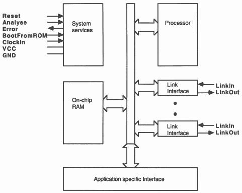
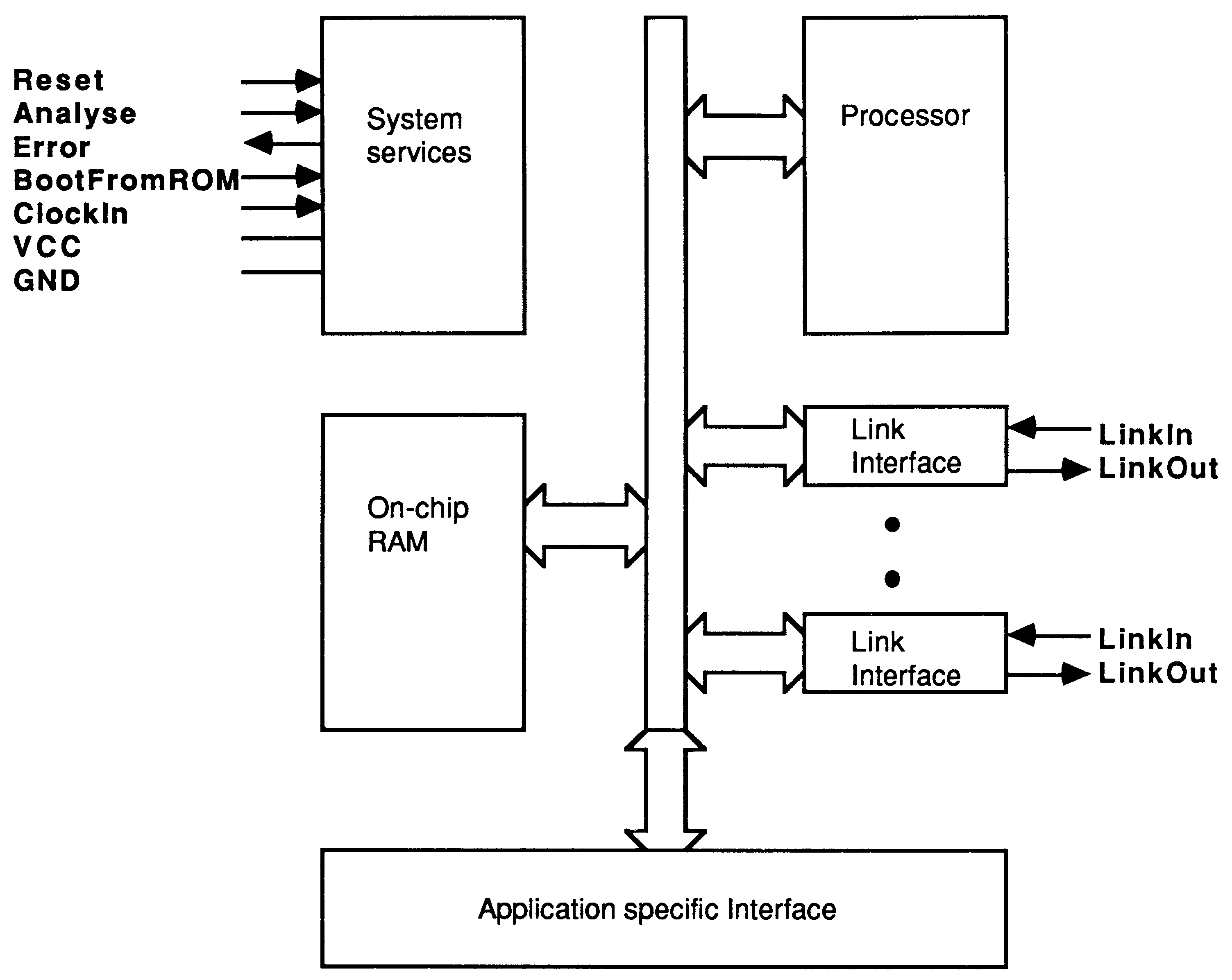
The INMOS transputer [1] is a family of VLSI microcomputers with processor, memory, and communication links for direct connection to other transputers on a single chip. Transputers may also include application specific hardware. The general architecture of the transputer family is shown in Figure 1. Highly parallel systems can be constructed from collections of transputers which operate concurrently and communicate through links. To provide maximum communication bandwidth with minimum hardware the transputer uses point to point serial communication links.
The transputer instruction set has been designed for the efficient and simple compilation of high level languages. Transputers can be programmed in sequential languages such as C, PASCAL and FORTRAN. However the occam language (see Section 2.5) allows the programmer to fully exploit the facilities for concurrency and communication provided by the transputer architecture.
The on-chip memory is not a cache, but part of the transputer’s total address space. It can be thought of as replacing the register set found on conventional processors, operating as a very fast access data area and program store.
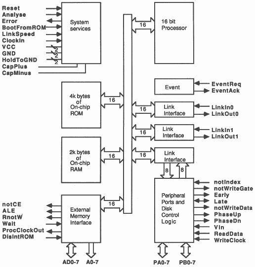
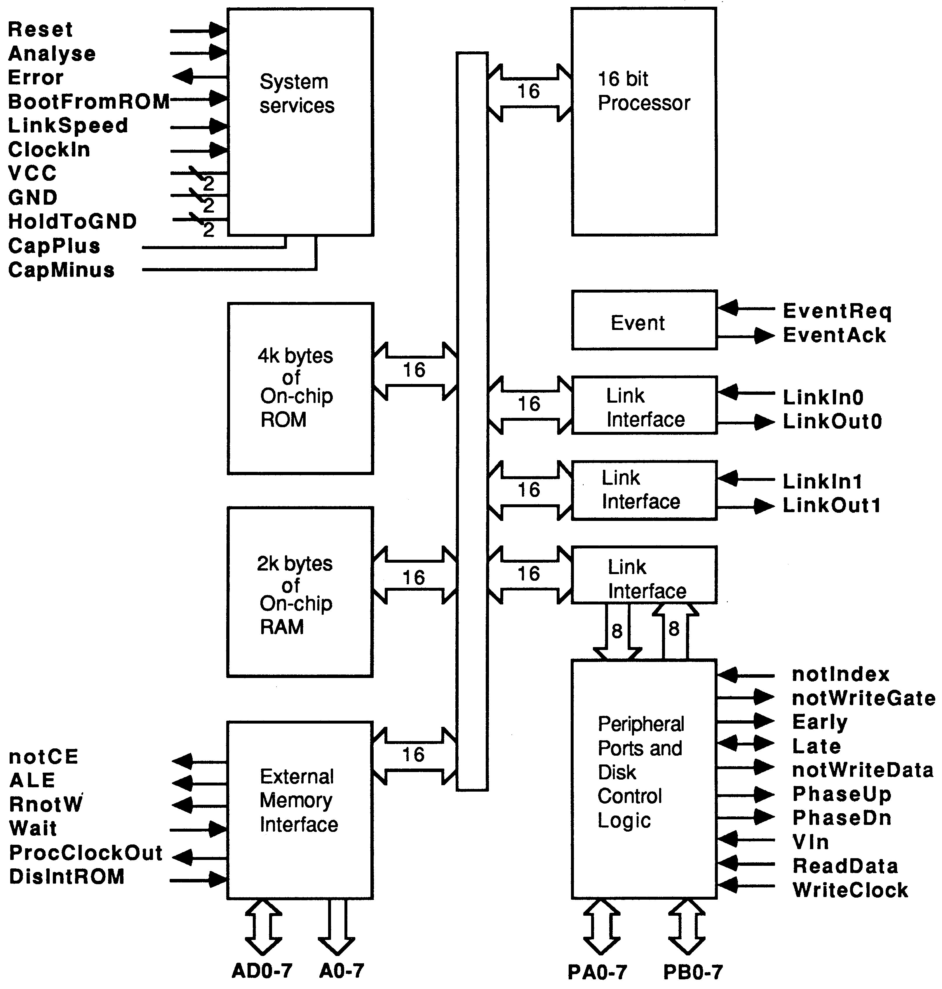
The IMS M212 [2] is a transputer containing the same 16 bit, 10 MIPS (million instructions per second) processor as the IMS T212 but with the addition of hardware for peripheral control applications, see Fig 2.2. This interface provides two general purpose 8 bit parallel ports or an interface to up to 4 disk drives.
The disk interface has been designed to provide easy connection to disk drives using standard interfaces. There is sufficient flexibility to allow a wide variety of drive types and formats to be used. Both Winchester disks compatible with the ST506/ST412 interface and SA400/450 compatible floppy drives are supported. The disk interface logic provides all the necessary functions on-chip, such as data separation and hardware for error detection and correction.
The IMS M212 also includes two 20 MHz INMOS serial links, 2 Kbytes of RAM, 4 Kbytes of ROM and an external memory interface which can be used to extend the total memory available to 64 Kbytes. The on-chip ROM contains software to allow the IMS M212 to be used as a stand-alone disk controller, with commands and data being transferred across the serial links. Alternatively, the internal ROM can be disabled and the disk processor programmed in a high level language.
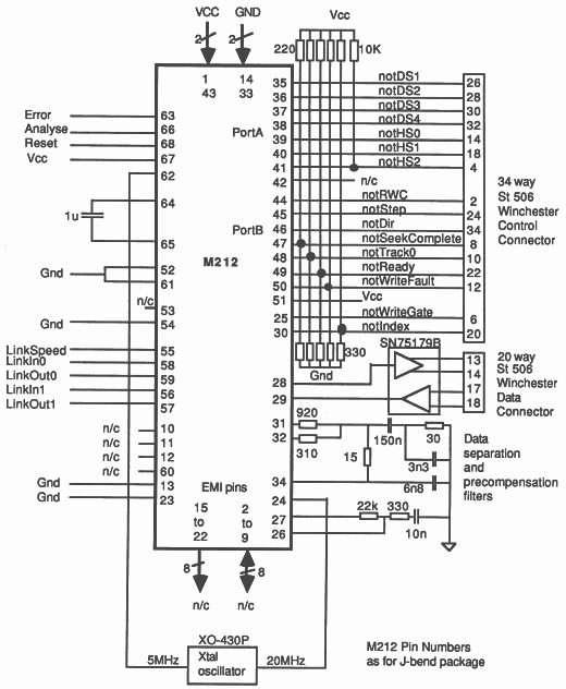
The IMS M212 can be interfaced to Winchester or floppy disks with very few external components. Figure 3 shows a typical circuit for use with Winchester disks. This system can either be used in Mode 1 (described in the next section) or booted from one of its links.
The internal ROM program can be used to control disk operations by sending it commands and data down a link and reading results and data back from the link. This is known as Mode 1 operation and provides a very simple way to implement a Winchester and floppy disk controller. Mode 2 operation, where the disk processor is programmed in a high level language, provides greater flexibility and the ability to offload some of the file system operations from the main processor in a system.
The systems described in this note use the IMS M212 in Mode 1, i.e. the internal ROM is enabled and commands are sent down one of the transputers serial links. This provides the simplest way of getting a system working.
For each drive the IMS M212 maintains a block of data containing all the required control information for that drive. Each byte of control data is called a parameter; a number of parameters are common to all drives. When a drive is selected the parameters for that drive are made accessible, this is then the current drive. Commands are sent as byte values followed by zero or more data bytes. The commands supported are shown in Table 1.
|
The IMS B005 is one of the range of INMOS evaluation boards. It is a double extended eurocard containing an IMS M212 with 64 Kbytes of static RAM, a 20 Mbyte Winchester, and a 3.5 inch floppy disk drive. This allows the use of the IMS M212 in a transputer system with no further hardware design. Using the disk controller in Mode 1 allows data on the drives to be read and written with very simple software.
The occam language enables a system to be described as a collection of concurrent processes which communicate with one another, and with the outside world, via communication channels. Occam programs are built from three primitive processes:
| variable := expression | assign value of expression to variable |
| channel ? variable | input a value from channel to variable |
| channel ! expression | output the value of expression to channel |
Each occam channel provides a one way communication path between two concurrent processes. Communication is synchronised and unbuffered. The primitive processes can be combined to form constructs which are themselves processes and can be used as components of another construct.
Conventional sequential programs can be expressed by combining processes with the sequential constructs SEQ, IF, CASE and WHILE. Concurrent programs are expressed using the parallel construct Pox, the alternative construct ALT and channel communication. PAR is used to run any number of processes in parallel and these can communicate with one another via communication channels. The alternative construct allows a process to wait for input from any number of input channels. Input is taken from the first of these channels to become ready and the associated process is executed.
This note contains some short program examples, including a few written in occam. These should be readily understandable but, if necessary, a full definition of the occam language can be found in the occam reference manual [3].
MS-DOS is the most widely used operating system on IBM personal computers and compatibles. It was originally derived from CP/M but adds many features such as hierarchical directory structures and improved hardware independence. It is also supplied by IBM as PC-DOS. Version 2.0 of MS-DOS was released in March 1983 and contained many Unix-like features: the hierarchical file structure; I/O redirection and pipes. Version 3 became available in 1984 and included improved support for hard disks; the code described in this note was written for, and has only been tested under, versions 3.1 and 3.2.
Like most operating systems MS-DOS is split into several modules. This allows
the hardware dependent parts to be isolated from the kernel or body of the
operating system and the kernel from the user interface.
The three layers in MS-DOS are:
Assembler level programs can call these functions via software interrupts. High level languages, such as C, generally provide a library of routines to access the systems functions.
| CON | The console (display and keyboard) |
| PRN | Line printer output |
| AUX | Auxiliary I/O device |
| CLOCK | The real time clock and calendar |
Device drivers are the modules of an operating system which control the hardware. They isolate the other parts of the system from the peculiar characteristics of particular devices. The terms resident and installable are used to distinguish between drivers built into the BIOS and those loaded at system boot time. The DOS kernel makes I/O requests to the device drivers, the driver then translates these into the necessary commands to the hardware to perform the desired action.
In many operating systems all the device drivers are embedded in the body of the kernel making modification or extension of the system very difficult. One of the most powerful features added to MS-DOS versions 2 onwards is the installable device driver. These are used with the system configuration file (CONFIG. SYS), which is read on startup, to load extensions to the operating system to handle new or non-standard devices. This allows a user to easily customise the machine. Also, from the programmers point of view, there is a well defined interface with the hardware independent DOS kernel which allows any device to be interfaced to MS-DOS without requiring any special knowledge about the internals of the operating system.
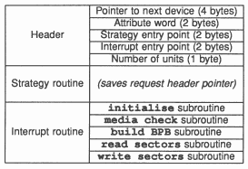
A device driver consists of three sections: a header; the strategy routine; and the interrupt routine (see Figure 4). MS-DOS stores device drivers as a linked list, and the first item in the header is a pointer to the next device. The header also contains an attribute word, which describes the type of the device, and pointers to the entry points of the strategy and interrupt routines.
The strategy routine is called (via the pointer in the header) by MS-DOS when the device is loaded and subsequently whenever an application program performs I/O to the device. MS-DOS passes a pointer to a data structure called a request header which contains details of the operation to be performed. The strategy routine does not actually service these requests but simply saves the pointer for later use by the interrupt routine.
The interrupt routine is called by MS-DOS, immediately after the call to the strategy routine, and services the I/O request. This routine is the main part of the driver and will normally consist of a number of subroutines to implement the requested action. The same data structure that is used to pass the parameters of the request is also used to return an error/status flag and other results. The first call is always with an initialise request which causes the device driver to perform any necessary initialisation and report back its memory usage requirement to MS-DOS. The initialisation code will never be executed again so it is normally placed at the end of the program so that the memory occupied by it can be reclaimed by MS-DOS.
This apparently complex structure is intended to support future upgrades of MS-DOS to a mufti-tasking operating system. Full details of the structure of, and interface to, an MS-DOS device driver can be found in Advanced MS-DOS [8].
A disk device driver receives requests at the read-sector/write-sector level; MSDOS maintains file pointers and directory structures and translates these into logical sector addresses. However, in order to implement and debug a device driver, it is helpful to have an understanding of how disks are structured.
MS-DOS disks are organised in a fixed way that is very easy to use. Each disk is presented as one or more logical volumes with a drive code (A, B etc), an optional volume label, a root directory and a number of files and subdirectories. MS-DOS provides functions which allow programmers to access files without being concerned with the details of how the data are physically stored on the disk. Requests for file operations normally go through two levels of translation in order to access the disk data:
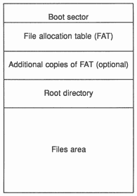
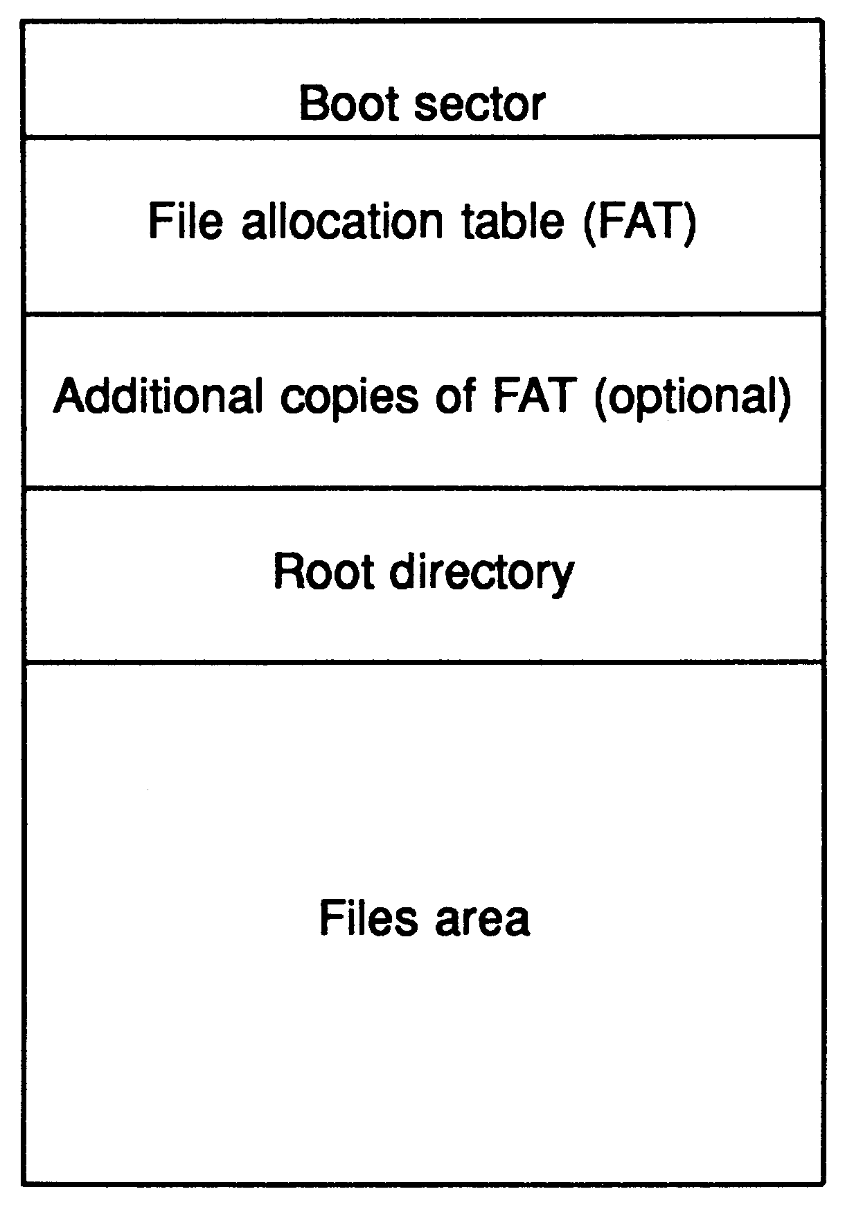
Each MS-DOS logical volume is divided into a number of fixed size system areas and the files area (see Figure 5), The size of the various system areas can vary between different disk types and computers but there is enough information in the boot sector to interpret the structure of any particular disk. The contents of the system sectors are written when the disk is formatted.
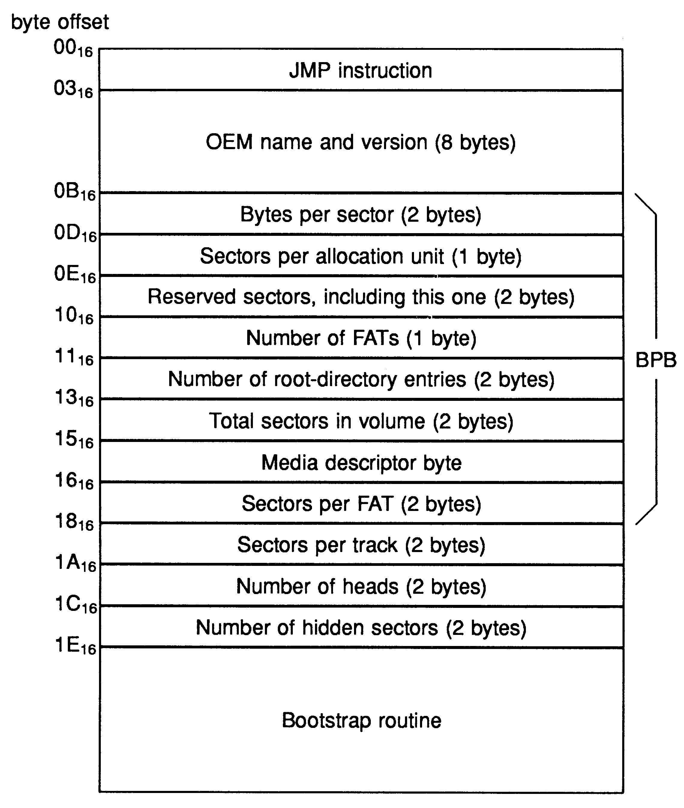
Logical sector zero is known as the boot sector and contains all essential information regarding the layout of information on the disk (see Figure 6). The first 3 bytes form an 8086 jump instruction, the destination of which is the entry point of the bootstrap code at the end of the sector. If this disk is used to bootstrap the computer then sector zero is read into memory and execution transferred to the bootstrap code via the jump. Following the jump instruction is an 8 byte field which is used by the system manufacturer for an identification string.
The next 19 bytes contain the BIOS parameter block (BPB). This contains all the values required by MS-DOS to find the other system areas and calculate the mapping from file level accesses to logical sector addresses. Immediately following this are three 2 byte values which contain other disk format information, this is not used by MS-DOS but is intended to help the device driver translate from logical sectors to physical disk addresses. Finally the rest of sector zero is taken up with the bootstrap program.
The boot sector is only the first sector of a reserved area that can be one or more sectors long. The size of this reserved area is specified by the reserved sectors word in the BPB.
The file allocation table (FAT) is used to record how sectors are assigned to files and directories. MS-DOS allocates sectors from the files area of the disk to files in ’clusters’ or ’allocation units’. The number of sectors in a cluster is a power of 2 and is specified in the sectors per allocation unit byte. Each entry in the FAT corresponds directly to a cluster. In version 3 of MS-DOS each entry may be 12 or 16 bits long, depending on the number of sectors on the disk. If the disk contains less than 4087 clusters then the FAT entries are 12 bits long, otherwise they are 16 bits. The first two entries in the FAT are always reserved. On IBM compatible disks the first 8 bits of the first entry contain a copy of the media descriptor byte - this defines the type of disk - a copy is also present in the BPB in the boot sector. The remainder of the reserved bytes contain FF16.
The entries in the FAT after the reserved bytes record how clusters are used. The directory entry for a file contains the number of the first cluster assigned to that file. This is also used as a pointer into the FAT and, from that point on, each entry in the FAT contains the number of the next cluster in the file until a last cluster value is encountered. Other FAT entry values have special meanings: a value of zero indicates an unused cluster and there are values to indicate bad sectors.
For maximum data security it is usual to have more than one copy of the file allocation table. These are updated simultaneously by MS-DOS and if a read of a sector in one copy of the FAT should fail another copy is tried.
Disk directories contain information about, and pointers to, all the files on the disk. The root directory, unlike its subdirectories, is of fixed size and is in a fixed position on the disk. The size and position of the root directory can be determined from the BPB.
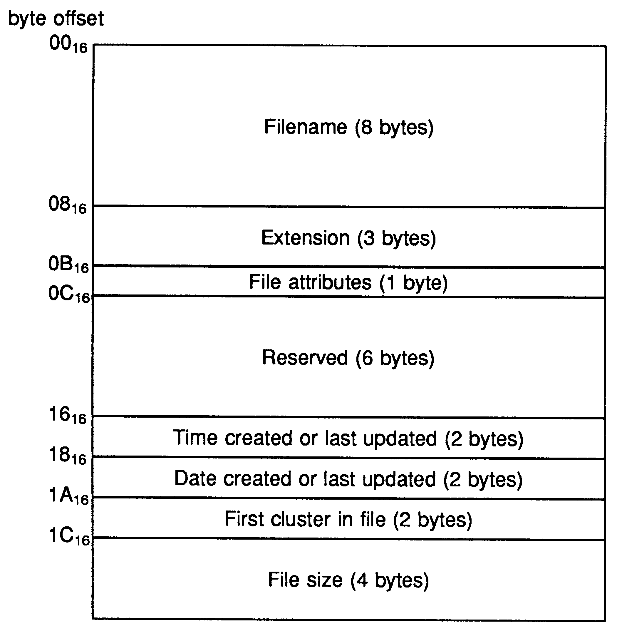
The internal structure of all the directories is, however, the same. Each file has a 32 byte entry in a directory; this defines the filename and extension, the file attributes, the time and date the file was created or last updated, a pointer to its first cluster and the file size. The structure of each entry is shown in Figure 7.
The attribute byte records information about this entry, such as whether it is a file or a subdirectory, whether it is write protected etc.
The rest of the disk is used for storing files and subdirectories. Space is allocated from the files area when a file or subdirectory is created or extended. When a large number of files have been created, edited, deleted etc. then new files may become fragmented, i.e. the clusters they are allocated will be spread out over the disk. The next cluster is found by reference to the FAT. This can slow access to data because the disk heads will have to be moved more frequently.
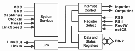
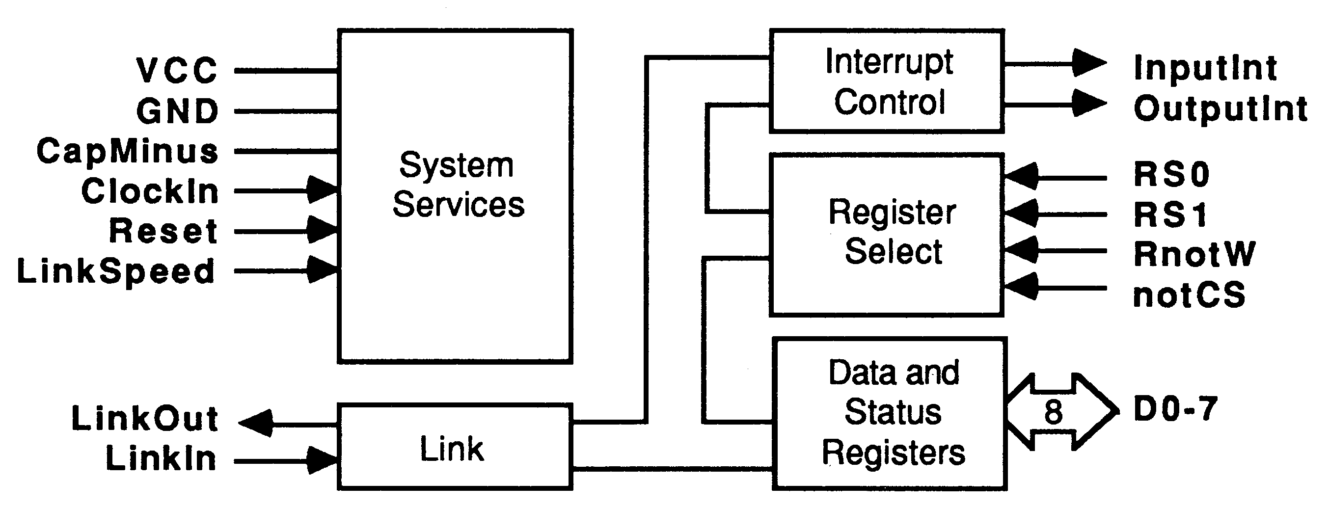
The simplest way to allow a non-transputer system to communicate with a transputer is to provide it with an INMOS serial link. This is done with a link adaptor, a device which converts between 8 bit parallel data and INMOS serial link format. Two versions of the link adaptor are available, the IMS C011 converts between a serial link and two byte-wide, handshakes ports. The other, the IMS C012 (Figure 8), has a standard microprocessor bus interface to allow processors such as the 8086 family to communicate with transputers. Full details of these devices can be found in the transputer reference manual [1].
The IMS C012 has four registers as shown in Table 2. These consist of a read-only data input register, a write-only data output register and a read/write status register for each.
|
The input status register contains the data present flag and an interrupt enable control bit for received data. The data present bit is set to indicate that the input data register holds valid data. The output status register contains the output ready flag and an interrupt enable control bit for output data. The output ready bit is set to indicate that the output data register is empty.
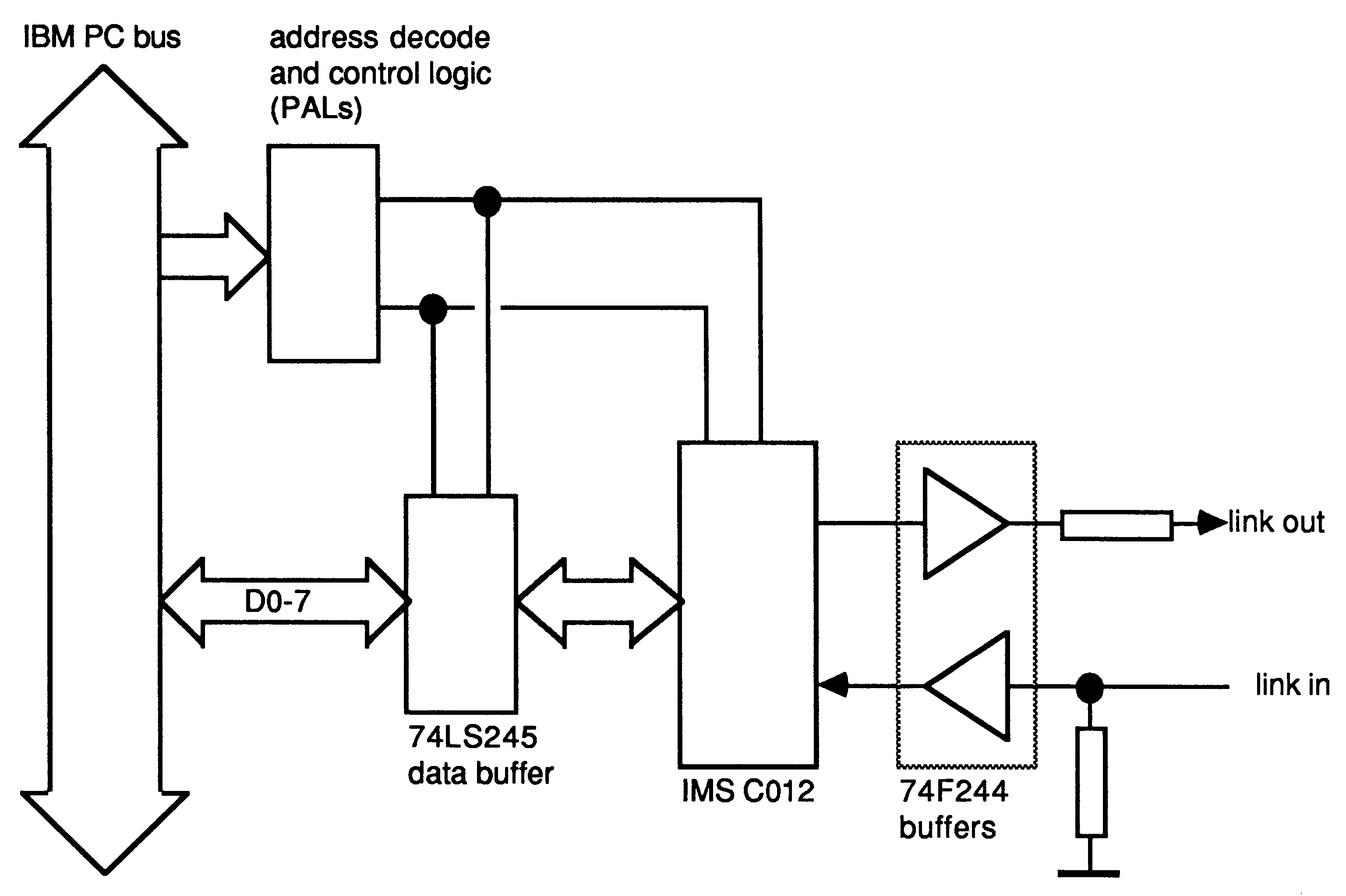
The IMS C012 is used on the IMS B004 and IMS B008 development boards for the IBM PC. In order to interface to the IMS M212, exactly the same circuit as on the IMS B004 was used but with the address decoding modified to select the link adaptor at a different I/O address. This allows the disks accessed via this link adaptor to be used at the same time as the transputer development system (TDS) running on an IMS B004.
A simplified diagram of the interface between the PC bus and the link adaptor is shown in Figure 9. The address decoding and other timing signals are generated in two of the PALS (programmable logic arrays) on the board. The base address of the link adaptor on the IMS B004 is 15016; the link adaptor used to communicate with the IMS M212 is addressed at 20016.
More details of the IMS B004 interface can be found in the board reference manual and in another INMOS Technical Note [5].
In order to communicate with the link adaptor, a set of macros were written which write bytes to, or read bytes from, the appropriate I/O port. Note that the base address of the link adaptor is kept in a variable, LinkBaseAddress, this is initialised, when the device driver is installed, from a parameter on the DEVICE = command line in the CONFIG. SYS file. This allows several link adaptors at different addresses to be accessed by installing multiple copies of the device driver. The device driver code was written using the Microsoft macro assembler.
The first two macros are used to poll the status registers while waiting for input data to arrive or output data to be transmitted:
StatusBit equ 1
; offsets of registers LinklnDataReg equ 0 LinkOutDataBeg equ 1 LinkInStatusReg equ 2 LinkOutStatusReg equ 3 ; waitForOutReady ; wait for the ouput ready bit to be set in link adaptor ; Input parameters: ; None ; Output parameters: ; None ; Registers used: ; dx used to read status register waitForOutReady macro local loop mov dx, [LinkBaseAddress] add dx, LinkOutStatusReg push ax loop: in al, dx and al, StatusBit jz loop pop ax endm ; waitForDataPresent ; wait for the data present bit to be set in link adaptor ; Input parameters: ; None ; Output parameters: ; None ; Registers used: ; dx used to read status register waitForDataPresent macro local loop mov dx, [LinkBaseAddress] add dx, LinkInStatusReg push ax loop: in al, dx and al, StatusBit jz loop pop ax endm |
Then there are two macros for sending and receiving bytes, as shown below:
; BYTEfromLink
; read a byte from the link adaptor and return in al ; Input parameters: ; None ; Output parameters: ; al contains the byte read from the link ; Registers used: ; al, dx used to read the byte BYTEfromLink macro waitForDataPresent mov dx, [LinkBaseAddress] add dx, LinkInDataReg in al, dx endm ; BYTEtoLink ; send a byte down the link ; Input parameters: ; al contains the byte to be written ; Output parameters: ; None ; Registers used: ; al, dx used to write the byte BYTEtoLink macro waitForOutReady mov dx, [LinkBaseAddress] add dx, LinkOutDatafeg out dx, al endm |
Other data types, such as 16 bit integers or arrays of sector data, are transferred using multiple instances of the byte transfer macros. Note that the BYTEtoLink macro polls the output ready bit first and then writes the data to the output register. This allows the 8086 to continue processing while the link adaptor transmits this data byte; when the 8086 has another byte to send it checks the status register first to ensure the previous byte has been sent. In fact, even when doing block transfers of data, the link data rate is faster than the 8086 can move data to or from memory so it is really only necessary to synchronise on the first byte of each message.
The program uses variations of these basic macros which allow timeouts or user interrupts (using the Break key) during data transfers.
The device driver for the IMS M212 only needs to handle a subset of the the possible I/O requests from the DOS kernel. This is because some commands are only used by serial I/O devices and others are optional. Each command has a number of parameters in the request header; these specify which drive is being referred to, the number of sectors to be transferred etc. The commands supported are:
The initialise request causes the device driver to reset and initialise the link adaptor and IMS M212. The driver tests for the presence of an IMS M212 by sending a read parameter command and waiting for a reply. If either the output, or the following input fail, then a value is returned that stops MS-DOS installing the driver. If an IMS M212 is present then a sequence of commands is sent to initialise it and set up the parameters for the MS-DOS disk format. Generally the IMS M212 defaults for the Winchester and floppy parameters are used with the exceptions shown in Table 3.
When a media check request is received the driver should return a code to indicate if the disk has changed since it was last accessed. In general it is not possible far the driver to tell if a floppy disk has been swapped so the following strategy is adopted: if the drive referred to is a floppy disk drive then the disk may have changed value is returned; if the drive is a Winchester then the disk has not changed value is returned. If it is told that the disk may have changed then MS-DOS will read sectors from the disk, rather than using values cached in RAM.
Build BPS requests the driver to return a pointer to the BIOS parameter block in the driver. This contains the information required for MS-DOS to calculate the sector addresses of the various data areas on the disk. In the case of the floppy disk drive, the BPB is read from disk to ensure the array of values pointed to is consistent with the current disk. The values for the Winchester are held in a table in the device driver.
The read sectors request causes a number of sectors to be read from the specified disk into a buffer in RAM, the data transfer area. This is done by sending a number of read sector and read buffer commands to the IMS M212. The Error and Reason parameters in the IMS M212 are read after each read sector operation. If an error has occurred then no more reads are performed, the appropriate MS-DOS error code (see Table 4) is written to the status word and the number of sectors successfully read is returned.
The write sectors command instructs the device driver o transfer data from RAM o the specified disk. This uses the write buffer and write sector commands, again the error flags are checked after each operation.
|
|
The IMS M212, used in Mode 1, has a logical addressing mode in which disk addresses are specified as logical sectors. This maps exactly onto the requests made of the device driver by MS-DOS and greatly simplifies the code of the device driver. The driver simply has to select the specified drive and then attempt to transfer the requested number of sectors. The driver also has to translate any error values returned by the IMS M212 into the equivalent MS-DOS error codes.
In order o provide a complete set of software tools for using the IMS B005 as an extra PC disk a few extra support programs were written. These included some test programs, e.g. o read and display the contents of a disk sector, and some useful utilities. These were mainly written in Turbo Pascal (version 4.0).
The procedures and functions for accessing the link adaptor were compiled as a ‘unit’ or library which scan be linked with each application program. As an example here are the routines for reading and writing bytes to and from the link adaptor (the identifier port is a predefined array in Turbo Pascal which is mapped onto I/O address space). These routines are equivalent to the assembler code given in Section 4.1.2. The variable linkBaseAddress contains the base address of the link adaptor and is initialised at the start of the program.
const
inputData = 0; outputData = 1; inputStatus = 2; outputStatus = 3; procedure outByte (b : integer); begin while not odd (port[linkBaseAddress + outputStatus]) do begin { do nothing (wait for output ready bit to be set) } end; port[linkBasekddress + outputData] := b; end; function inByte : integer; begin while not odd (port[linkBaseAddress + inputStatus]) do begin { do nothing (wait for data present bit to be set) } end; inByte := port[linkBaseAddress + inputData]; end; |
Further routines allow the transfer of other data types and perform I/O with a time-out (useful if a link connection, or the program being communicated with, might not be reliable).
A program to format disks on the IMS B005 is essential and was one of the first programs written. This program formats Winchester or floppy disks, performing a low-level format (using the IMS M212 format track command) and then writing the following data in the system sectors:
Another useful program ’parks’ the heads of the Winchester disk, i.e, moves them to a shipping track near the centre of the disk. This is to avoid the risk of loss of data when the power is turned off and the heads land on the surface of the disk.
The initial ’one PC - one IMS B005’ system described above has been extended to provide multiple users with access to a shared disk system. An ITEM1 rack containing a number of IMS B005 boards is connected to each user’s PC via transputer link cables. The programs and data stored on these disks are available to all of the users. This allows common software and libraries to be moved from the individual PC’s Winchester disks onto the shared disk store. To avoid inconsistent data being read by a user, each PC normally only has read access to each drive. When new files are to be installed on a drive, one PC is temporarily allocated write access. This locks out all other users from reading or writing the disk until the file copying is complete. Afterwards all other PCs are forced to perform sufficient extra sector reads to ensure that any cached data they may have is consistent with the disk.
This system can be easily extended to allow other shared resources, such as a printer which would be accessed via a character device driver. In future, as more users are added in more distant locations, it may be convenient to provide a mail facility between users.
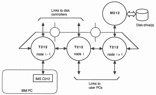
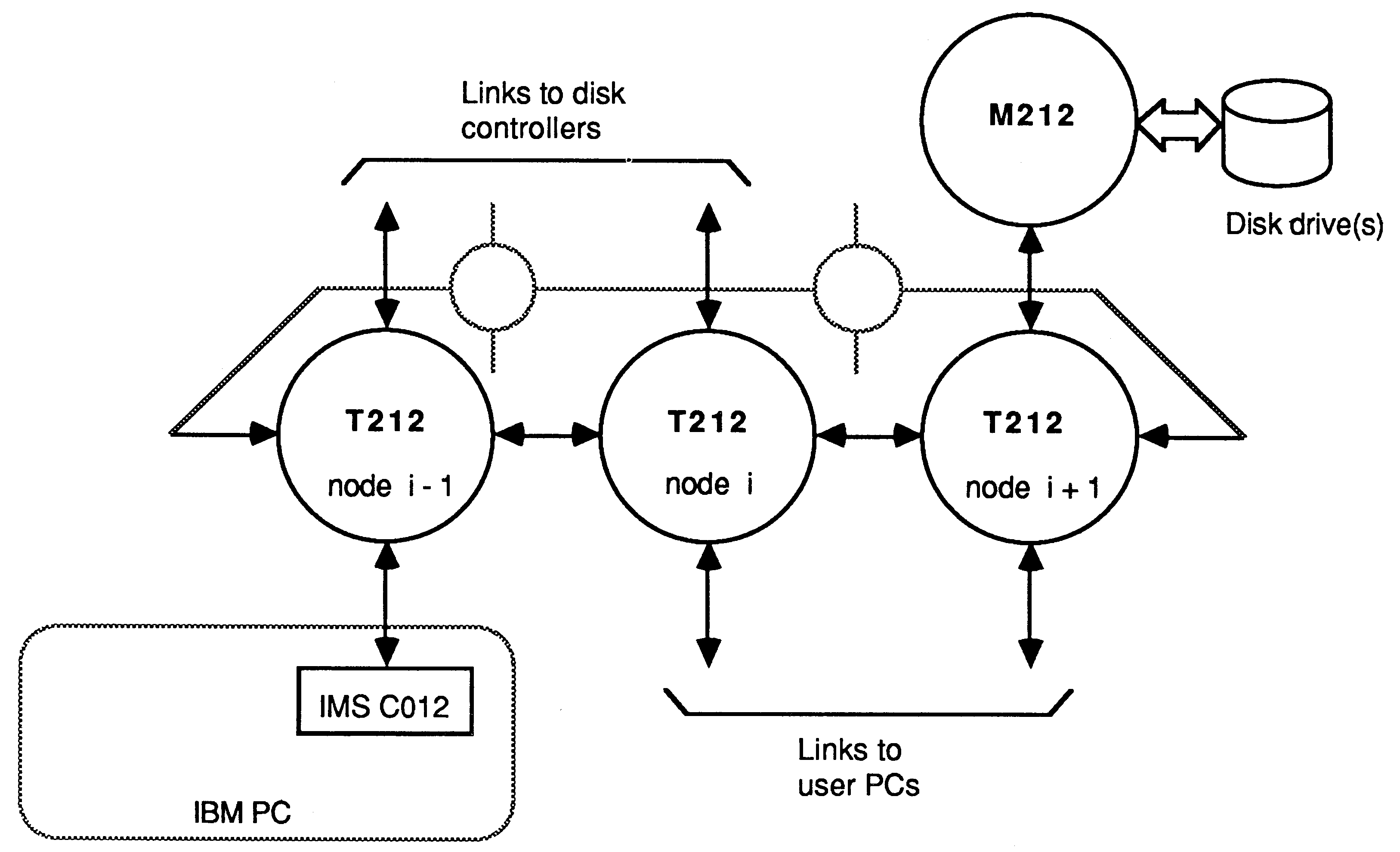
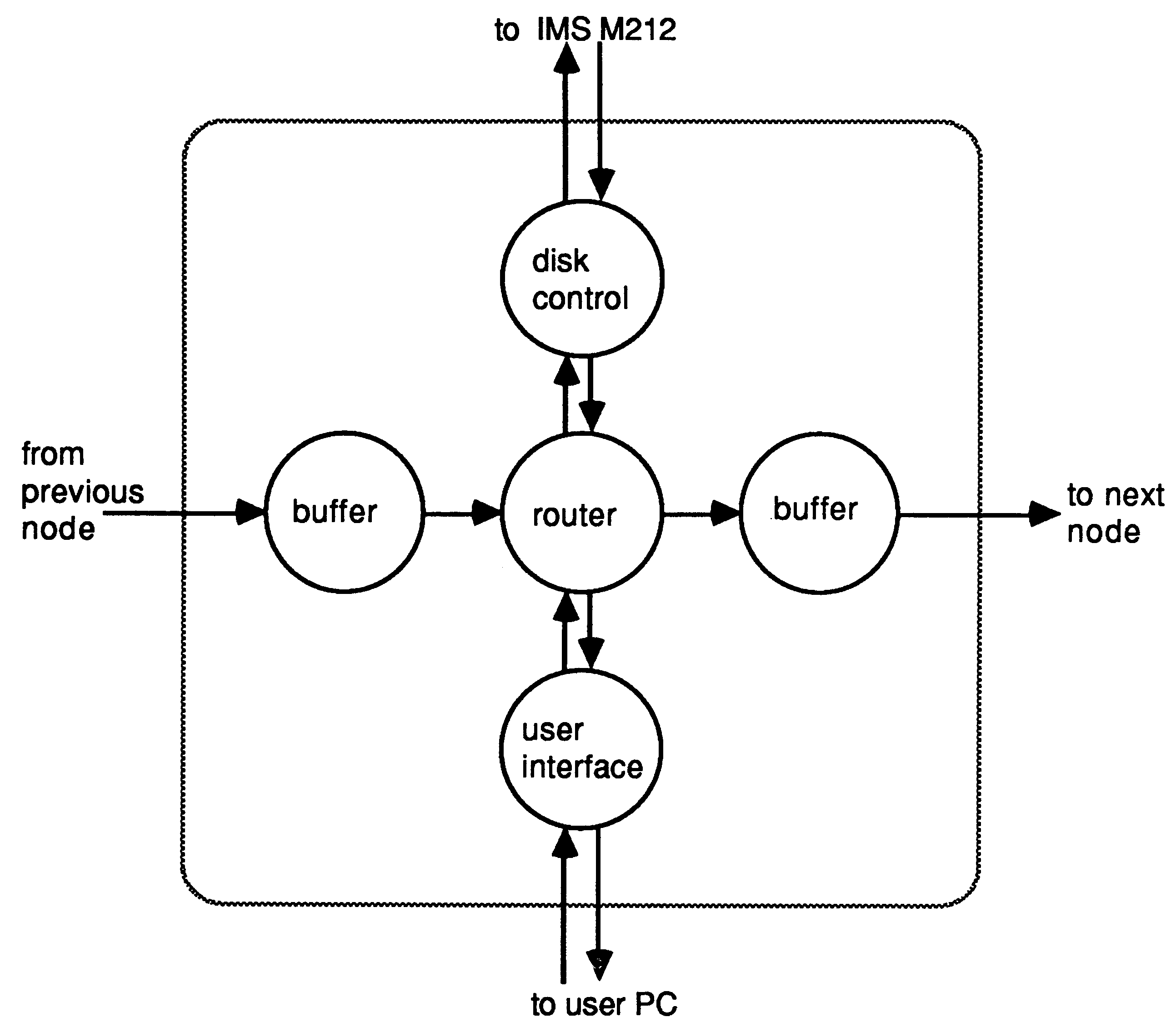
In order to allow read/write requests from any user to any disk, the shared disk system is implemented with a ring of IMS T212s for routing commands and data. Each of these nodes then has one link available for connection to an IMS M212 and one link for connection to a user PC. This is shown in Figure 10. This topology has the advantages of simplicity: the routing software on each node simply has to decide whether a request or reply is for the disk or PC connected to this node otherwise the command is simply passed on to the next node. It also allows the system to be built from standard INMOS evaluation boards; an IMS B012 motherboard with 16 IMS B402 modules. This allows up to 16 disks and 15 PCs to be connected using one IMS B012 board, this number can easily be increased by adding more boards and modules.
Currently all the PCs connected to the disk network are in fairly close proximity (all in one room) and the link connections are made via twisted pairs. The link outputs on the IMS B012 have series termination and it has been calculated that this will allow links to be used over distances up to 10 metres. For greater distances the signals will require some sort of buffering, see the appropriate INMOS Technical Note [6] for more details of these calculations.
The IMS B402 is one of the range of INMOS transputer modules. These modules have an IMS T212 and 8 Kbytes of static RAM (this gives a total of 10 Kbytes including the transputers on-chip RAM). The module has 16 pins which supply power, control and dock signals to the transputer and provide connection to the transputers serial links. A full specification of transputer modules can be found in another INMOS Technical Note [7].
The IMS B012 is a double extended eurocard with sockets for 1 6 transputer modules such as the IMS B402. There are also two IMS C004 link crossbar switches controlled by an IMS T212, this allows a wide range of interconnection topologies to be implemented under software control. The connections can be changed by sending control data to the link switches down a configuration link.
One of the two connectors on the back of the board gives access to a pair of links at each end of a pipeline which goes through the transputer modules, and to the IMS T212 controlling the link switches. In this application the two ends of the pipeline are connected together to give a ring of processors. The link switches can then be programmed to provide two link connections from each module to the second edge connector. These links are used to connect to the IMS B005 boards and the user PCs.
This system is inherently more complex than the simple system described in Section 4. However, this complexity is made manageable by the use of the occam programming language. This language was specifically designed for describing and programming systems made up of many communicating processes. The use of occam for the control software means that the device driver, which is written in assembler, can be far simpler. The use of occam also allows a large amount of security to be built into the system.
The control of message routing is entirely distributed around the system. There is no central database or controller with information about the drives and users connected. Each node in the network makes decisions based on its own local status and either services requests locally or passes them on to be handled elsewhere (it neither knows nor cares if or where they are serviced). Each node is identified by an identification number, id, which is passed as a component of each message.
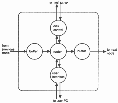
The control software has two main tasks: routing disk access requests from users; and interfacing to the disks. The first action performed by each node in the system is to determine if a disk is connected. This is tested in the same way as described in Section 4.2. In this case the occam standard library InputOrFail.t() and OutputOrFail.t() [4] are used to timeout the communications with the IMS M212. The result of this test is passed as a parameter to the routing process described below (Section 5.2.2). Next the main part of the code is entered; this consists of a number of parallel processes as shown in Figure 11.
Messages requesting a disk read or write are routed around the system with a protocol consisting of: a command tag; the id value of the sender; the destination drive and then any other parameters required. Replies are similar, generally consisting of the tag; the original sender’s id; and a status/error code followed by any other parameters. Values are all of type BYTE or iNT16, this removes the problem of communicating between different word length machines. A subset of the protocol definition is shown below:
PROTOCOL network.p
CASE -- write request; source; drive; sector number; sector data sectorWriteReq; BYTE; BYTE; INT16; [BytesPerSector]BYTE -- write ack; dest; status sectorWriteAck; BYTE; INT16 -- read request; source; drive; sector sectorReadReq; BYTE; BYTE; INT16 -- read ack; dent; status; data sectorReadAck; BYTE; INT16; [BytesPerSector]BYTE : |
Further details of occam communication protocols can be found in [3].
The message routing process solves two problems:
The three input sources are multiplexed together via an occam alternative process [3]. An alternative is a way of waiting for input from any one of a number of input channels:
ALT
chan1 ? message ... process 1 chan2 ? message ... process 2 chan3 ? message ... process 3 |
In this example, the ALT process will wait for the first of the three input channels to receive a message and will then execute the corresponding process. This operation is supported very efficiently in the transputer hardware and no processor time is used while waiting for a message. Each of the input statements, or guards, can also have a boolean condition attached to it. This allows certain input channels to be effectively disabled depending on the state of the system. This is very important for preventing deadlock, one of the biggest problems in concurrent systems. As an example consider:
ALT
(count > 0) & chan1 ? message ... process 1 ready & chan2 ? message ... process 2 chan3 ? message ... process 3 |
In this example the input from chant will only be enabled when the value of the variable count is greater than zero; the input from chant is only enabled when the boolean variable ready has the value TRUE.
The messages received by the router, from each of the three sources, are basically treated identically. The only difference being that messages from the attached PC have the value of the node id inserted in the message.
A routing decision is made for each message based on the type of message, and the source and destination values. There are basically two classes of message (as described in Section 5.2.1); requests and acknowledgements.
A check is also made for messages which have gone right round the ring without being routed to their destination. This may occur because the requested drive does not exist, for example. This situation is indicated by the source id in the message being equal to the id of the current node. When this type of error is detected (it can only realistically occur with requests to drives) an acknowledgement is generated by the router to return an appropriate error code (no such drive) to the user who initiated the request.
To prevent deadlock occurring when several users make requests of the same drive simultaneously, it is necessary to add a boolean guard to the ALT in the router. If this is not done the disk control process may be unable to get a reply out to the router because the router has received a message for the control process. But the router cannot forward this message to the control process because the control process is not ready to receive a message until it has output its reply to the router.
ALT
-- request from user (NOT diskBusy) & fromuser ? CASE ... set diskBusy := TRUE if request for this disk -- message from ring (NOT diskBusy) & inRing ? CASE ... set diskBusy := TRUE if request for this disk -- a result back from disk (diskBusy AND drivesConnected) & fromDisk ? CASE ... route result and reset diskBusy flag |
The guard on the ALT prevents the router accepting messages from either the user or the previous node in the ring when a reply is pending from the disk controller. This may occasionally cause a slight bottleneck as replies cannot be routed through a node while that node is processing a disk request, but this is far better than the system stopping completely.
Because of the simplicity of the decisions to be made at each node, routing processes like this are very easy to implement in occam with a high degree of confidence in their correctness. The use of a protocol across channels and guarded inputs in alternatives, eliminate the most common causes of deadlock in communicating processes. The compiler is able to perform checks that both processes using a channel are performing compatible outputs and inputs. The boolean guards in the ALT prevent the router attempting to send a message to the disk controller whilst it is attempting to talk to the router.
The disk control process performs most of the work that would normally be done by a device driver. Because it is written in a high level language it is easier to implement, can provide greater functionality and be more securely checked (both at compile time and run time).
The main functions of this process are:
The last of these is an example of a useful feature which is very simple to implement in occam using an ALT. In this case one of the guards, rather than being a normal input, is a special kind of input from a timer [3]. For example, the input clock ? AFTER t will wait until the value of the timer clock is later than the value of t. This delayed input can be used to generate a known time delay with no processor overhead.
SEQ
clock ? now clock ? AFTER now PLUS delay |
This sequence inputs a value representing the current time to the variable now; the delayed input then waits until the value of clock is later than now PLUS delay. More usefully, a delayed input can be used in an alternative to provide a timeout on a channel input:
SEQ
clock ? now ALT char ? message ... do something with message clock ? AFTER now PLUS timeout ... no message within timeout; do something else |
This sequence will wait for an input from the channel char for the period of time specified by timeout.
In the disk control process an ALT like the above is used to wait for disk requests from the router. If no requests are received within the specified time then the Winchester heads are moved to the shipping track. If this feature were to be provided in the simple device driver described earlier it would require an interrupt handler for the MS-DOS timer to be installed as well as the device driver. This would share a variable count with the device driver - count would be set to zero whenever the drive was accessed and incremented on each tick of the timer. When count reached some maximum value the drive’s heads would be parked. Interrupt handlers are notoriously difficult to write and debug and even this simple example shows how easy it is to solve problems involving time and communication using occam.
Processes to provide buffering on channels are very frequently used in occam programs to decouple channel communication from computation. This is a simple way of allowing the processor to continue processing while the link engines transfer data. In its simplest form a buffer will simply consist of:
BYTE b :
WHILE TRUE -- repeat for ever SEQ in ? b out ! b |
This simple loop will repeatedly input a byte value from one channel and output it on another. Normally at least one of these channels will be mapped onto transputer links. Buffer processes should be run as high priority processes so that messages can be passed on as quickly as possible. A buffer consumes very little processor time as all it has to do is initiate the communication which is then handled by the link engine.
In the program described here, the buffer process must handle the protocol described in Section 5.2.1, Using a CASE input makes this very straight forward. Each message, consisting of a tag and a sequence of values, is simply input and then output:
... declare variables used by buffer process
WHILE TRUE -- repeat for ever SEQ in ? CASE sectorWriteReq; source; drive; sector.number; sector.data out ! sectorWriteReq; source; drive; sector.number; sector.data sectorWriteAck; dest; status out ! sectorWriteAck; dest; status ... other cases |
This is also more efficient than the simple BYTE buffer above, as it can transfer arrays of data making best use of the autonomous link engines.
The user interface process has two functions: it provides a level of message buffering between the link and the router; and it allows for failure of the link to a user PC. This communication link is the least reliable in the system partly because of its length, but also because a PC may be turned on or off at any time generating electrical noise on the link.
This process communicates with the router process using the protocol described above, but simply transmits arrays of bytes to the PC. This is done using the InputOrFail.t() and OutputOrFail.t() library procedures [4] which support communication through unreliable channels. If a communication fails then two things must be done: the link logic on the transputer must be reset (using another library procedure Reinitialise()); and the the processes at each end of the link must be resynchronised. This is done by exchanging a special sequence of messages until the expected values are received and returned.
The IMS C004 link switches on the IMS B012 board are used in a rather odd way; each transputer link connection consists of two wires and on this board each wire goes to a different IMS C004. The simplest configuration is for connections straight through the IMS C004s i.e. linkln; to linkOut; for all links on each switch. This brings all the required link connections out to the edge connector. A process running on the IMS T212 which controls the link switch sends the necessary commands to the IMS C004.
The device driver is much simpler than that in Section 4 as most of the work - generating IMS M212 commands, checking for errors etc. - is done in the occam program. The driver communicates with the network using the occam communication protocol, i.e it simply translates from DOS kernel requests to the appropriate protocol messages. However, no checking is done of tag values received; it is assumed that the network is sufficiently secure to send only the data expected at any time. Generally, each routine in the driver simply has to send a byte (corresponding to the value of the relevant protocol tag) followed by the necessary parameters extracted from the request header. The id field of the message is sent, in order to comply with the protocol, but the value is not meaningful. The driver then waits for the reply to come back from the network, the tag and id are input but ignored, then the results of the operation are read from the link and simply put into the appropriate fields of the request header.
To allow for communication failure the link I/O routines check for an MS-DOS break key (control-C or control Break) whilst polling the link adaptor status registers. This allows the user to regain control if the link fails. If this sort of exit is made from the device driver it is then necessary to run a program on the PC to resynchronise the communications with the network (see Section 5.2.5).
Although the current system performs adequately, there are a number of areas where optimisations could be made. If data is read continuously from a Winchester disk then quite high data rates can be achieved (typically 500 Kbytes per second). However, in a realistic situation, this performance is hard to achieve because of head movements required to locate the data. There are two reasons for moving the heads when reading an MS-DOS disk: (i) to refer back to the directory and FAT entries to locate files and sectors within files; (ii) to locate the next sector of the file when it becomes fragmented across the disk.
MS-DOS does some caching of sectors which reduces the number of accesses to the FAT on disk. If the disk control process kept copies of commonly accessed data (the FAT, root directory, etc.) in a cache then performance could be further improved. Similarly, when MS-DOS requests a sector, the next request will probably be for the next sector in that duster which means it may be efficient for the disk control process to cache clusters (or maybe even entire tracks). Data caching has not been added to the system as it stands because of the use of the IMS B402 module which has only 10 Kbytes total memory space. To add caching as described would require at least an extra 37 Kbytes of buffer space (16 Kbytes for the root directory and 21 Kbytes for the FAT) and more if cluster caching were to be implemented (at least one cluster would have to be cached for each user). The program could be run on modules with more memory (e.g. an IMS B404 with an IMS T600 32 bit processor and 2 Mbytes of RAM) however this is probably overkill in terms of cost and would reduce the maximum number of users and disks as the modules are bigger.
In a multi-user system, there will be even more head movement as disk requests from the various users (almost certainly for different sectors) are interleaved. A solution to this is to sort the requests to minimise head movement. This may cause some requests to be delayed for too long so the sorting algorithm must take this into account. Again this has not been implemented due to lack of memory in the current system.
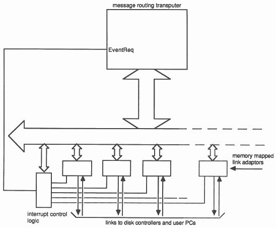
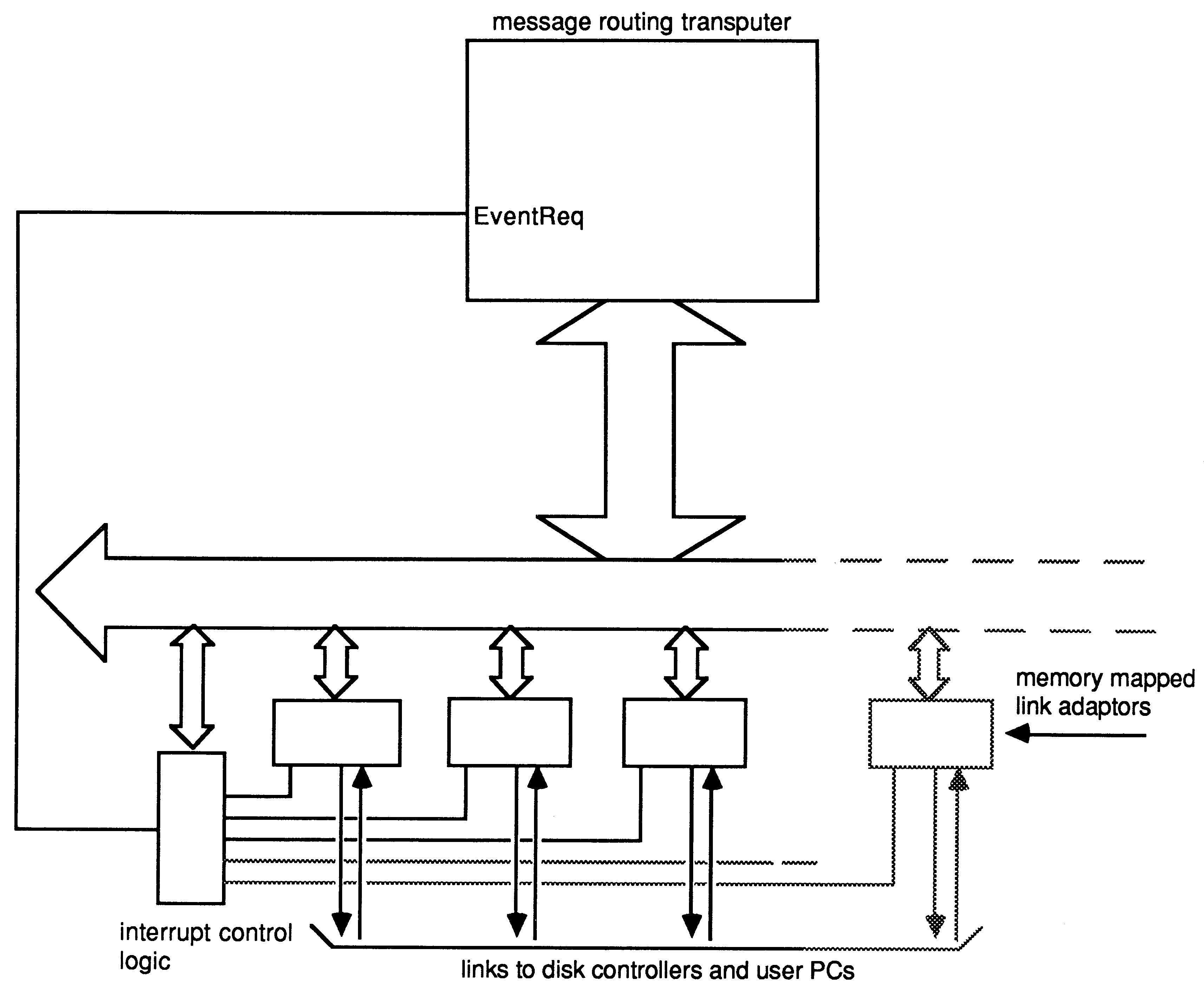
An alternative and more cost effective implementation is to have a single transputer to provide all message routing facilities and move the disk control code onto the IMS M212. The central routing processor would have to be a 32 bit device (e.g. an IMS T414) in order to provide the required amounts of memory. It would also require more than the 4 links on the transputer so a number of link adaptors would be memory mapped to provide a number of ’virtual’ links. These virtual links could be used very nearly as efficiently as the internal links if the interrupt outputs are connected, via an interrupt controller, to the EventReq pin of the transputer. The EventReq acts like an interrupt to the transputer but appears to the programmer simply as a channel input. This makes event handlers on the transputer very easy to implement and test, as they are exactly the same as any other piece of code. After receiving the event input, the transputer would read the number of the link adaptor generating the interrupt and then simply transfer the data. An outline of this scheme is shown in Figure 12.
This section summarises of some of the things which can cause problems when using the IMS M212 or programming for MS-DOS.
These fall into two groups:
SEQ
... toM2 ! writeParameter; Error; 0 ... |
The mistake here is that the number 0 is assumed to be of type INT unless otherwise specified:
SEQ
... toM2 ! writeParameter; Error; 0(BYTE) ... |
This note has described how it possible to add extra disk drives to a typical MS-DOS based system using the IMS M212 disk processor. The advantages of the IMS M212 in this application are:
This single disk system was then extended to allow multiple users shared access to a number of centrally located disk drives. This system used an array of IMS T212s to route commands and data from users to the appropriate disk. The advantages provided by this system are:
Both of the systems described here were constructed from standard INMOS evaluation cards and are being used by a number of people within INMOS.
The shared disk system can easily be extended to allow other shared resources to be attached (e.g. a printer) and to allow data transfers between attached PCs. A small amount of extra work also needs to be done on the shared disk system to make it completely self contained. Currently the network code is loaded from one of the attached PCs, a better solution is to bootstrap the system from ROM or from one of the Winchesters. It is also possible to improve the interface to the PC to take advantage of interrupts and DMA (direct memory access) data transfer on the PC. These are supported on new IBM PC plug in evaluation board from INMOS, the IMS B008. Details of this interface will be found in the reference manual for that board.
[1] Transputer reference manual. INMOS Limited Prentice Hall
ISBN 0-13-929001-X
[2] IMS M212 disk processor product data. INMOS Limited
[3] Occam 2 reference manual. INMOS Limited Prentice Hall
ISBN 0-13-629312-3
[4] Extraordinary use of transputer links - Technical Note 1.
INMOS Limited
[5] IMS B004 IBM PC add-in board - Technical Note 11.
INMOS Limited
[6] Connecting INMOS links - Technical Note 18.
INMOS Limited
[7] Dual-inline transputer modules (TRAMS) - Technical Note 29.
INMOS Limited
[8] Advanced MS-DOS, Ray Duncan, Microsoft Press.
ISBN 0-914845-77-2