|
|
| Notes on Graphics Support and Performance Improvements on the IMS T800 _____________________________________________________________________ |
| Guy Harriman July 1987 |
A transputer is a microcomputer with its own local memory, and with links for interconnecting between transputers and other transputer family products.
The IMS T800 is a 64-bit floating point member of a family of transputers, all of which are consistent with the INMOS transputer architecture described in the transputer reference manual. It is based on the IMS T414 design, but includes certain improvements and additions.
A fast autonomous floating point unit (FPU) on the IMS T800 replaces the microcoded floating point support of the IMS T414B. The 64-bit floating point unit provides single length and double length operation according to the ANSI-IEEE 754-1985 standard for floating point arithmetic and is able to perform floating point arithmetic operations concurrently with the processor, sustaining in excess of 1.5 MegaFlops.
A number of improvements were made to the central processing unit (CPU), including the addition of a number of instructions to replace important code sequences, optimising their speed of execution. Graphics support was added in the form of block move instructions.
The improvements were designed to boost performance in some important application areas, such as general concurrent (parallel) processing, communications, and high speed graphics, beyond the floating point performance improvement provided by the FPU alone. To further enhance performance, the amount of single cycle access internal static ram has been doubled on the IMS T800.
Significant improvement in link performance has been made possible on the IMS T800. The links were redesigned to double the data throughput by allowing the acknowledge packet to be sent before the data packet has been fully received.
This technical note on the IMS T800 begins by introducing the graphics support instructions, with an example of their use. It gives the results of the Whetstone benchmark for floating point performance, describes the implementation and speed of CRC generation, and compares the link performance of the IMS T800 with the IMS T414B.
Further details of the Whetstone benchmark system referred to in this document can be found in Technical Note 27.
The IMS T800 has special instructions provided to support graphics, in addition to the support provided for floating point arithmetic.
Pixels may be represented by single or multiple bytes in the graphics memory. They can be rapidly drawn, by overlaying, in such a way as to produce complex images.
The three new graphics instructions which have been added are concerned with moving a two-dimensional block of data from source to destination. The instructions differ in how the source and destination data are combined. The instruction move2dall replaces the original values of the destination bytes with the values of the source bytes. The instruction move2dnonzero only replaces the original value of each destination byte with the value of the corresponding source byte if the source byte is not zero (the colour black) in value. The third instruction, move2dzero, only replaces the original value of each destination byte with the value of the corresponding source byte if the source byte is zero in value.
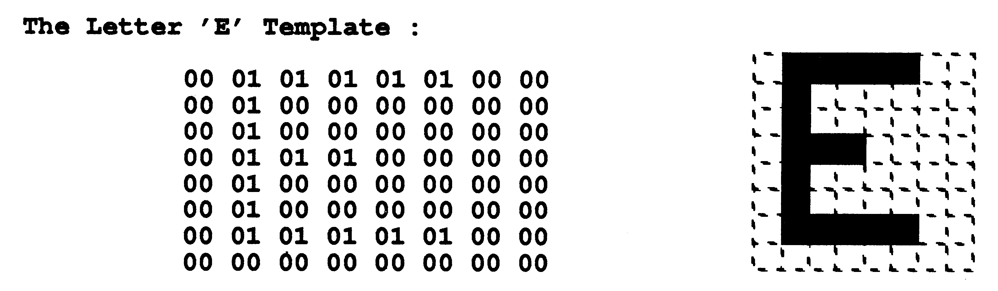
To illustrate this technique for graphics, the following example may be made. If it is required to display the letter E in striped colours, as seen through a keyhole, the graphics instructions may be easily applied to this task.
Three templates or predefined arrays of source data are needed in order to form the letter E in striped colours, through a keyhole. A template of the letter is taken from a table held in memory. This table would hold all the characters in as many type faces and as many orientations as required by the application. If the characters are held as an 8 by 8 byte array, its hexadecimal representation might be
|
|
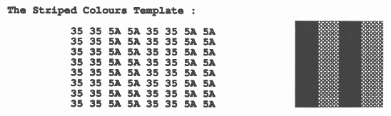
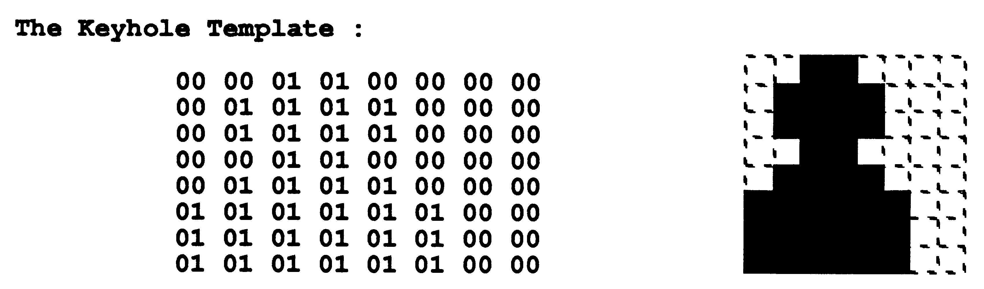
A separate 8 by 8 byte array would hold the striped colours. If the two required colours have byte values #35 and #5A, for example, it would be held as
|
|
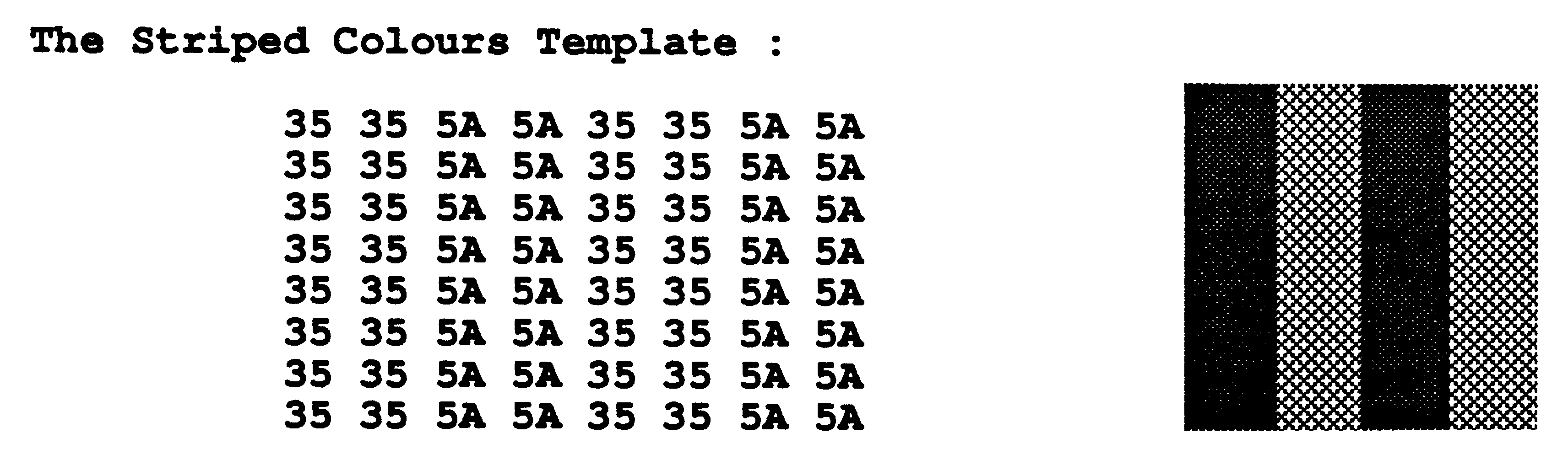
A third template would be the mask of a keyhole, and might look like
|
|
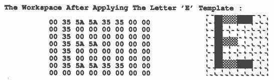
The first operation is to copy the striped colour template to a workspace area using move2dall. Then the letter E is applied to this workspace area by copying the E template to the workspace using move2dzero. The workspace now looks like
|
|
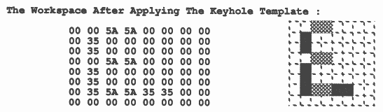
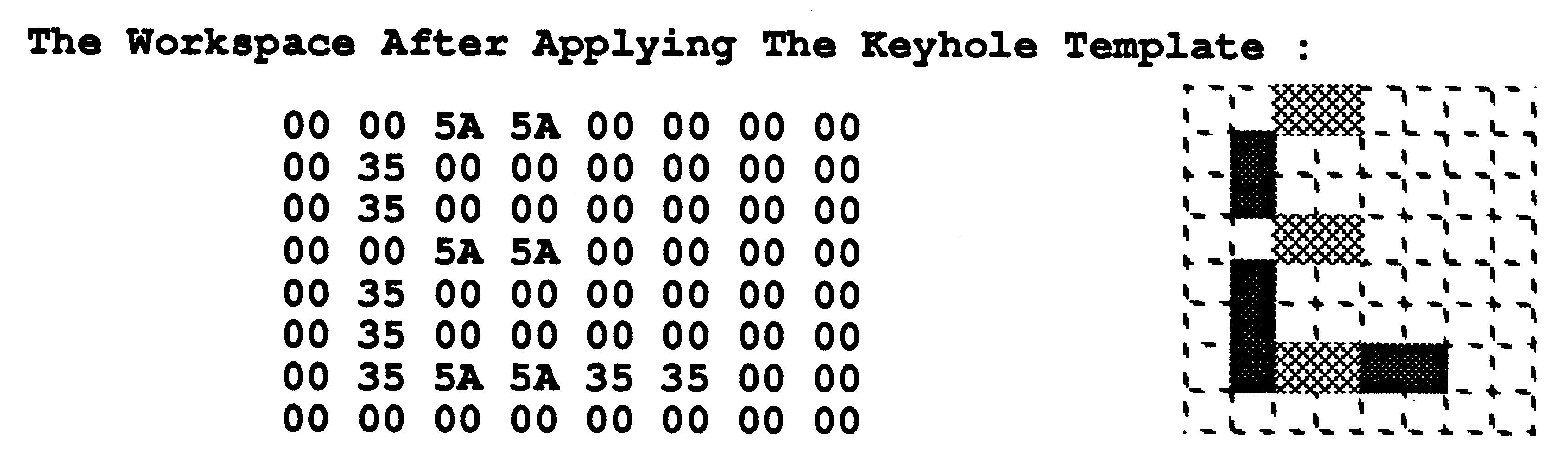
Next, the keyhole template is copied to the workspace using move2dzero. The workspace now appears as
|
|
This final pattern can now be copied to the video ram display area for display on the screen using move2dall.
A total of four moves have been made to make up this complex pattern on the screen. If the internal ram is used as the workspace area and for the keyhole and striped colour templates, the 16 reads and writes in the copying only take 32 processor cycles. When move2dnonzero and move2dzero are used, and none of the bytes need to be written to the destination in a word, the write operation itself is inhibited and takes two processor cycles to occur instead of the number of processor cycles in the memory access.
In order to improve on the performance, it may be legitimate to hold characters in store with the striped colour already applied to them, and to only apply the keyhole template at execution time. This would remove one of the move2dzero operations from the four moves used above.
From this example it can be seen that such functions as arbitrarily shaped overlapping windows may be achieved by the consecutive application of the graphics instructions. The instruction move2dnonzero is useful in the case of putting one image partially on top of another. The instruction move2dzero is useful when it is required to clip an image to a certain shape.
Taking a colour workstation application using an IMS T800-20, with a screen resolution of 1024 by 1024 8 bit pixels, four cycle (200 nSec) dynamic ram and video ram, and displaying characters which are defined to be 16 by 16 pixels, each character requires (4 * 16) words to be transfered to the video ram. The size of the table for 80 characters would be (16 * 16 * 80) bytes, that is 20 Kbytes. Assuming that half of the words in the character table have all four bytes of zero value, and that the character table is held in the external dynamic ram, there will be 4 * 64 cycles spent in reading the character from the table. There will also be, on average, 2 * 64 cycles spent on writing the character to video ram. For every row in the move2dall instruction there will also be an overhead of about 12 cycles. The total number of processor cycles taken to display one character will therefore be approximately
(4 ∗ 64) + (2 ∗ 64) + (12 ∗ 16) = 576
The time taken for an IMS T800-20 is therefore 28.8 microseconds per character. A screen of 1000 arbitrarily positioned characters can be drawn in 28.8 milliseconds, that is a screen refresh rate of 35 times per second.
The function of these two-dimensional block move instructions may best be described by occam PROCs.
PROC Move2D (VAL[][]BYTE Source, VAL INT sx, sy,
[][]BYTE Dest, VAL INT dx, dy, width, length) SEQ y = 0 FOR length [Dest[y+dy] FROM dx FOR width] := [Source[y+sy] FROM sx FOR width] : |
This moves a block of size width, length which starts at byte Source[sy][sx] to the block starting at byte Dest[dy][dx].
The Move2D procedure is implemented by the instruction move2dall.
PROC Draw2D (VAL[][]BYTE Source, VAL INT sx, sy,
[][]BYTE Dest, VAL INT dx, dy, width, length) BYTE temp: SEQ line = 0 FOR length SEQ point = 0 FOR width SEQ temp := Source[line+sy][point+sx] IF temp = (BYTE 0) SKIP TRUE Dest[line+dy][point+dx] := temp : |
This moves a block of size width, length which starts at byte Source[sy][sx] to the block starting at byte Dest[dy][dx]. However, for every byte transferred a check is made to see if it is zero. If this is the case then that byte is not copied, and the destination remains unaltered.
The Draw2D procedure is implemented by the instruction move2dnonzero.
PROC Clip2D (VAL[](]BYTE Source, VAL INT sx, sy,
[][]BYTE Dest, VAL INT dx, dy, width, length) BYTE temp: SEQ line = 0 FOR length SEQ point = 0 FOR width SEQ temp := Source[line+sy][point+sx] IF temp = (BYTE 0) Dest[line+dy][point+dx] := temp TRUE SKIP : |
This moves a block of size width, length which starts at byte Source[sy][sx] to the block starting at byte Dest[dy][dx]. However for every byte transferred a check is made to see if it is zero. If this is the case then that byte is copied.
The Clip2D procedure is implemented by the instruction move2dzero.
Draw2D and Clip2D are complementary. Draw2D is used for the copying of irregular shapes onto the screen. Clip2D is used in the creation of templates, where non-rectangular shapes are masked out from a picture. Complex shapes can be formed easily by multiple use of Draw2D and Clip2D to form images, before copying the shape with Move2D to a video frame buffer for display.
Six parameters are required to perform two-dimensional block moves. They are
The instruction move2dinit sets up three of these parameters in the reserved workspace in internal memory between #80000048 (above the interrupt save space) and #80000070 (MemStart). Three words of the reserved workspace are used for low priority two-dimensional block moves, and three other words of the reserved workspace are used for high priority two-dimensional block moves. On entry to move2dinit the stride of the source array is in the Creg, the stride of the destination array is in the Breg and the length is in the Areg. The three instructions move2dall, move2dnonzero and move2dzero contain on entry the address of the first source byte in the Creg, the address of the first destination byte in the Breg and the width in the Areg.
The occam procedures and the equivalent instructions were executed with code and data in external memory for a range of array sizes on an IMS T800A. This IMS T800A-20 was put on an Inmos B004 evaluation board having four cycle external memory, and operated at 20 MHz processor cycle frequency. All the benchmarking was done at high priority, in order to prevent the screen and keyboard handling from timeslicing the execution of the program, and to give access to the high priority timer which has a resolution of one microsecond.
The size of the destination array was 1024 by 1024 bytes. The source arrays were not initialised, and so contained an arbitrary number of zero value bytes. Therefore it is not relevant to compare the times taken for Clip2D and Draw2D for any array size. However, the relative performance for each array for the procedure and the equivalent instructions for Clip2D and Draw2D are based on identical initial conditions, and these may be meaningfully compared.
The following results were obtained:
| Source | Type of | Time For | Time For |
| Array Size | Move | Procedure | Instruction |
| 512 * 512 | Move2D | 30318 μsec | 27015 μsec |
| 512 * 512 | Draw2D | 1595661 μsec | 18262 μsec |
| 512 * 512 | Clip2D | 2359623 μsec | 26227 μsec |
| 256 * 256 | Move2D | 8502 μsec | 6839 μsec |
| 256 * 256 | Draw2D | 399061 μsec | 4702 μsec |
| 256 * 256 | Clip2D | 590293 μsec | 6551 μsec |
| 8 * 8 | Move2D | 72 μsec | 14 μsec |
| 8 * 8 | Draw2D | 442 μsec | 14 μsec |
| 8 * 8 | Clip2D | 579 μsec | 14 μsec |
| 1 * 1 | Move2D | 16 μsec | 4 μsec |
| 1 * 1 | Draw2D | 20 μsec | 3 μsec |
| 1 * 1 | Clip2D | 16 μsec | 4 μsec |
It can be seen that the overhead of doing one-dimensional block moves and a replicated SEQ in the Move2D occam procedure falls from 500% for an 8 * 8 array to 12
It can also be seen that the overhead of detecting zero value bytes and conditionally storing them one a time in Draw2D and Clip2D compared with the use of move2dnonzero and move2dzero increases from a factor of 30 for an 8 * 8 array to a factor of 90 for a 512 * 512 array.
The advantage of using the graphics instructions instead of dedicated hardware is the flexibility that software offers. The performance provided should be adequate for many applications, but it is of course easy to linearly increase this performance by adding more IMS T800’s to a system, giving each a proportion of the video ram to draw into. It is most straightforward to divide the screen in the way in which the video ram chips are partitioned. The serial port of the video rams can be connected up as they would be with a single IMS T800 as a processor.
The Whetstone program is often used to compare the floating point performance of machines, as it contains a ’normal’ mixture of accessing data structures, integer arithmetic, and floating pointing arithmetic.
For this benchmark, an IMS T800B was put into a B004 IBM PC/AT evaluation board running with four cycle external memory. The transputer development system (TDS) was run on the IMS T800B, and the T800 compiler was used to compile the Whetstone benchmark program, which was then loaded and run on the IMS T800B.
The Whetstone program (Randell and Russell, 1964) consists of eleven modules, each of which contains a loop. The number of times the loop is executed is called the weighting of the module. The modules were designed to provide a good fit to the statistics of language usage by the choice of the following loop count values:
| Module | Purpose | Internal Loop |
| Number | Of Module | Count (Weighting) |
| 1 | Simple Identifiers | 0 |
| 2 | Array Elements | 12 |
| 3 | Array As Parameter | 14 |
| 4 | Conditional Jumps | 345 |
| 5 | Omitted | 0 |
| 6 | Integer Arithmetic | 210 |
| 7 | Trig Functions | 32 |
| 8 | Procedure Calls | 899 |
| 9 | Array References | 616 |
| 10 | Integer Arithmetic | 0 |
| 11 | Standard Functions | 93 |
The zero weightings were given because in these cases the best fit of the benchmark to the statistical analysis showed that the weightings should have been negative.
The Whetstone program was translated into occam exactly as prescribed by the original. All procedure calls were preserved, and all 11 of the original modules were used, including those that are not executed in the standard itself (modules 1, 5, and 10) so that the code size was that of the standard. None of the expression orders were modified to make them quicker to execute.
The program was executed at high priority, to allow the high priority processor clock to be read. This clock has a resolution of one microsecond, while the low priority has a resolution of 64 microseconds. After each module had completed execution, the timer was read.
The program includes five transcendental functions (sin, cos, arctan, log, and exponential), and the compiled size for the occam version is such that both the code and data fit in 3.5 Kbytes. It is therefore possible to run the benchmark in internal memory.
Ten iterations of the Whetstone loop give one million Whetstones. The time taken for ten iterations for single length data, with the effect of internal and external (four cycle access) memory is shown below :
| Data | Position of | |||
| Length | Code | Data | Module | Execution Time |
| Single | Internal | Internal | 1 | 0 μsec |
| Single | Internal | Internal | 2 | 1212 μsec |
| Single | Internal | Internal | 3 | 9175 μsec |
| Single | Internal | Internal | 4 | 8194 μsec |
| Single | Internal | Internal | 5 | 0 μsec |
| Single | Internal | Internal | 6 | 12810 μsec |
| Single | Internal | Internal | 7 | 52576 μsec |
| Single | Internal | Internal | 8 | 55290 μsec |
| Single | Internal | Internal | 9 | 27411 μsec |
| Single | Internal | Internal | 10 | 0 μsec |
| Single | Internal | Internal | 11 | 49523 μsec |
| Single | External | Internal | 1 | 0 μsec |
| Single | External | Internal | 2 | 1328 μsec |
| Single | External | Internal | 3 | 10436 μsec |
| Single | External | Internal | 4 | 13074 μsec |
| Single | External | Internal | 5 | 0 μsec |
| Single | External | Internal | 6 | 16381 μsec |
| Single | External | Internal | 7 | 73729 μsec |
| Single | External | Internal | 8 | 70612 μsec |
| Single | External | Internal | 9 | 38439 μsec |
| Single | External | Internal | 10 | 0 μsec |
| Single | External | Internal | 11 | 65878 μsec |
| Single | External | External | 1 | 0 μsec |
| Single | External | External | 2 | 1843 μsec |
| Single | External | External | 3 | 16130 μsec |
| Single | External | External | 4 | 17885 μsec |
| Single | External | External | 5 | 0 μsec |
| Single | External | External | 6 | 27140 μsec |
| Single | External | External | 7 | 97535 μsec |
| Single | External | External | 8 | 104797 μsec |
| Single | External | External | 9 | 68992 μsec |
| Single | External | External | 10 | 0 μsec |
| Single | External | External | 11 | 85066 μsec |
The time taken for ten iterations for double length data, with the effect of Internal and External (four cycle access) memory is shown below:
| Data | Position of | |||
| Length | Code | Data | Module | Execution Time |
| Double | Internal | Internal | 1 | 0 μsec |
| Double | Internal | Internal | 2 | 1494 μsec |
| Double | Internal | Internal | 3 | 11415 μsec |
| Double | Internal | Internal | 4 | 9228 μsec |
| Double | Internal | Internal | 5 | 0 μsec |
| Double | Internal | Internal | 6 | 16065 μsec |
| Double | Internal | Internal | 7 | 119385 μsec |
| Double | Internal | Internal | 8 | 79667 μsec |
| Double | Internal | Internal | 9 | 44349 μsec |
| Double | Internal | Internal | 10 | 0 μsec |
| Double | Internal | Internal | 11 | 95701 μsec |
| Double | External | Internal | 1 | 0 μsec |
| Double | External | Internal | 2 | 1649 μsec |
| Double | External | Internal | 3 | 13036 μsec |
| Double | External | Internal | 4 | 14195 μsec |
| Double | External | Internal | 5 | 0 μsec |
| Double | External | Internal | 6 | 21345 μsec |
| Double | External | Internal | 7 | 146688 μsec |
| Double | External | Internal | 8 | 89623 μsec |
| Double | External | Internal | 9 | 50137 μsec |
| Double | External | Internal | 10 | 0 μsec |
| Double | External | Internal | 11 | 108346 μsec |
| Double | External | External | 1 | 0 μsec |
| Double | External | External | 2 | 2446 μsec |
| Double | External | External | 3 | 21369 μsec |
| Double | External | External | 4 | 18402 μsec |
| Double | External | External | 5 | 0 μsec |
| Double | External | External | 6 | 31753 μsec |
| Double | External | External | 7 | 187389 μsec |
| Double | External | External | 8 | 141227 μsec |
| Double | External | External | 9 | 82790 μsec |
| Double | External | External | 10 | 0 μsec |
| Double | External | External | 11 | 139744 μsec |
The Whetstone ratings, formed by summing the execution times for the individual modules, are as follows:
| Data | Position of | Total | ||
| Length | Code | Data | Execution Time | MWhet/sec |
| Single | Internal | Internal | 216191 μsec | 4.63 |
| Single | External | Internal | 289877 μsec | 3.45 |
| Single | External | External | 419388 μsec | 2.38 |
| Double | Internal | Internal | 377304 μsec | 2.65 |
| Double | External | Internal | 445019 μsec | 2.25 |
| Double | External | External | 625120 μsec | 1.60 |
The Single length Whetstone rating for an IMS T800B-20 was shown to be 4.6 MWhetstones per second. The quoted figures for the benchmark are for the use of Internal memory. The effect of External memory on the execution times of the Single length Whetstone program was investigated to demonstrate the performance cost of executing floating point programs from External memory. However, the efficiency of compiled occam is such that even as large a program as the Whetstone program can fit into Internal memory.
The performance of the IMS T800A-20 was 3.8 MWhetstones per second. The IMS T800B-20 achieved a rating of 4.6 MWhetstones per second by the use of three-bits-at-a-time floating point multiplication-instead of the two-bits-at-a-time multiplication used on the IMS T800A, and by the use of TIMES instead of ’*’to do integer multiplication. TIMES in occam2 compiles to the prod instruction, whereas ’*’ compiles to the mul instruction. On the IMS T800B both small negative and small positive multipliers are executed quickly, in a time proportional to the bit position of the most significant bit set in the modulus of the multiplier. On the IMS T800A and IMS T414B only small positive numbers were treated in this way. The mul instruction always takes 38 cycles. The prod instruction, unlike the mul instruction, does not evaluate the overflow condition from the multiplication, but can be used to improve performance wherever error checking is not required. The compiler can always substitute prod for mul when the user selects ’REDUCED’ error checking in the compiler parameters, as overflow is ignored.
Further details of the Whetstone benchmark system referred to in this document can be found in Technical Note 27.
A group of four instructions was added to the IMS T800 to provide a method for efficiently generating cyclic redundancy checks (CRCs). These checks are based on the addition of a small amount of redundant information to the end of messages, and are generated in such a way that an error in the transmission of a message is most likely to be detected. The method uses the shifting and exclusive-oring of the message to produce a checksum in the same way that pseudo-random or maximal length numbers can be produced. This method can also be understood as the polynomial division of the message to produce a remainder, the message being treated as a single binary number. The polynomial divisor is known as the polynomial generator, and is chosen for an application for its particular properties. The remainder (checksum) has the property in polynomial division that when it is placed at the least significant end of the message, and the division is performed over both the message and the checksum, then the remainder is zero. It can therefore be understood that if both the message and the checksum are transmitted, and the division performed over both by the receiver, then the receiver can identify if the transmission was corrupted by the remainder not being zero.
In hardware, the implementation of the CRC is normally done with a shift register of the required bit length, and exclusive-or gates connected to give the effect of the polynomial generator. Thus the bit length of the checksum and the value of the polynomial generator are fixed in the hardware.
The approach taken on the IMS T800 was to generate the CRC checksum in microcode, as this gave the user flexibility in the choice of bit length (up to a 32 bit word), and control over the choice of polynomial generator. As the function of checksum evaluation is division in which the conditional subtraction is replaced by conditional exclusive-oring, the logic and datapath structures which are used for integer division were used in the same way to perform polynomial division.
During the history of the development of communications standards, much confusion and incompatibility has been caused by the choice by different manufacturers of their definitions of the order of bit significance in the storage of data objects.
If the least significant bit of a data object is stored at the numerically smallest bit address, and all more significant bits are stored in ascending address order, the convention used is known as little-endian. On the other hand, if the most significant bit of a data object is stored at the smallest bit address, and all less significant bits are stored in ascending address order, the convention is known as big-endian. The INMOS transputer architecture convention is strictly little-endian.
There is an entire range of manufacturers’ conventions, from completely little-endian to completely big-endian. Many conventions are inconsistent within themselves, having for example bits within bytes ordered in one direction, but bytes within words ordered in the opposite direction.
The little-endian scheme dictates that the most significant bit of the message is held at the highest value address. This means that the message is stored in the same way as it would be if it was a binary number on which arithmetic was to be performed. As division is done by dividing the most significant part of the dividend, and proceeding to the least significant end of the dividend, it follows that polynomial division for the calculation of the checksum should start from the most significant bit of the message. The predefined procedure CRCFromMSB in the occam2 compiler library implements CRC generation starting from the most significant bit of an arbitrarily aligned byte string. The instruction crcword is used to apply the polynomial generator to each word-in the message beginning at the most significant word.
An example of a standard which starts the CRC calculation from the most significant end is called XMODEM. This standard uses a 16 bit checksum, with a CCITT (X.25) HDLC/SDLC generator polynomial #11021 (G(x)=x**16 + x**12 + x**5 + 1). This polynomial generator is passed as a parameter to CRCFromMSB as #10210000, as the most significant 16 bits of the 32 bit integer form the 16 bit CRC register. The order of bytes within an occam string must be reversed before applying CRCFromMSB. The result is left in the most significant 16 bits of the 32 bit integer CRCResult.
The following XMODEM test cases, where the strings are written in reverse order to occam strings, were used to check the correctness of CRCFromMSB:
InputString | Polynomial | CRC |
| Generator | Result | |
| ”T” | #10210000 | #1A710000 |
| ”EHT” | #10210000 | #1E0A0000 |
| ”9876543210,XOF,NWORB,KCIUQ,EHT” | #10210000 | #04980000 |
In order to check CRCs which have been generated according to the big-endian convention, the predefined procedure CRCFromLSB is provided. The predefined procedure CRCFromLSB in the occam2 compiler library implements CRC generation starting from the least significant bit of an arbitrarily aligned byte string. As the instruction crcword is used to apply the polynomial generator to each word in the message beginning at the least significant word, and crcword starts from the MSB, each word is bit reversed after being loaded in the CPU stack using the instruction bitrevword.
Two related examples of standards which start the CRC calculation from the least significant end are CCITTCRC and SDLC. These standards also use a 16 bit checksum, with the CCITT (X.25) HDLC/SDLC generator polynomial #11021 (G(x)=x**16 + x**12 + x**5 + 1), passed as a parameter to CRCFromLSB as #10210000, as the most significant 16 bits of the 32 bit integer form the 16 bit CRC register. The result is left in the least significant 16 bits of the 32 bit integer CRCResult. The difference between CCITT-CRC and SDLC is that in hardware the CRC register is initialised to #FFFF in SDLC. This prevents leading zeroes from being added to or deleted from the message without being detected by SDLC, as they do not effect MODEM or CCITT-CRC checksums. In order to correctly compute an SDLC checksum in software, the least two significant bytes of the message must be BITNOTed. If the message is only one byte long, then this byte and the least significant byte of the integer CRCResult must be BITNOTed.
The following CCITT-CRC test cases were used to check the correctness of CRCFromLSB:
InputString | Polynomial | CRC |
| Generator | Result | |
| ”T” | #10210000 | #000014A1 |
| ”THE” | #10210000 | #00007D8D |
| ”THE,QUICK,BROWN,FOX,0123456789” | #10210000 | #00007DC5 |
The rule of one’s-complementing the first two bytes of the string, or in the case of the one byte string ”T”, one’s-complementing the ”T” and the least significant byte of CRCResult, must be applied to generate SDLC. The following SDLC test cases were also used to check the correctness of CRCFromLSB:
InputString | Polynomial | CRC |
| Generator | Result | |
| ”T” | #10210000 | #00001826 |
| ”THE” | #10210000 | #000044BE |
| ”THE,QUICK,BROWN,FOX,0123456789” | #10210000 | #0000DF91 |
The CRC library procedures have been written to efficiently perform checksum calculation on arbitrarilyaligned byte vectors. As the most important uses involve large messages which tend to be placed in external memory, the message is taken in sixteen word chunks, and if the message is not already word aligned in memory, block moved into the vector []BYTE AlignedBuffer which is PLACED in the workspace of the CRC procedure. The purpose of doing this is to realign each chunk to a word boundary, and then to have fast access to the aligned chunk as the vector []BYTE AlignedBuffer would be held in internal memory. The instruction crcword is used in the optimum way in this section of the CRC procedures, as both the CRCResult and the PolynomialGenerator are left on the CPU stack after each word is read either directly from the message, or if it had to be block moved, from the []BYTE AlignedBuffer vector.
The words remaining from the message after all the complete sixteen word chunks have been processed are CRCed one word at a time. Finally any bytes left over from the message are CRCed one at a time with the instruction crcbyte. As the final bit of the message must pass all the way through the CRCResult register, the checksum is completed by using a word value of zero as data with the instruction crcword.
This is the occam2 source of the library procedure CRCFromMSB:
PROC CRCFromMSB (VAL []BYTE InputString,
VAL INT PolynomialGenerator, INT CRCResult) -- Comment -- The string of bytes is polynomially divided by the generator -- starting from the most significant bit of the most significant byte -- byte in decreasing bit order. -- All the bits in the string of bytes must be shifted through the -- CRC register, including the least significant bit of the string. -- VARS VAL []BYTE ZeroWord RETYPES [0] : VAL BPW IS SIZE ZeroWord : VAL BufferWordSize IS 16 : VAL BufferSize IS BufferWordSize * BPW : [BufferSize]BYTE AlignedBuffer : -- Assumes Byte vectors are word aligned PLACE AlignedBuffer IN WORKSPACE : INT Aligned : INT WordCount : INT ByteCount : INT Base : SEQ Base := SIZE InputString -- WordCount := WordSel(ByteCount) ByteCount := SIZE InputString GUY LDL ByteCount WCNT -- Areg := WordSel(Areg); Breg := ByteSel(Areg) STL WordCount STL ByteCount -- Aligned := &InputString[Base] /\ (BPW - 1)) GUY LDL Base LDLP InputString BSUB WCNT -- Areg := WordSel(Areg); Breg := ByteSel(Areg) REV STL Aligned -- CRC 16 Words at a time IF Aligned = 0 WHILE (WordCount >= BufferWordSize) SEQ Base := Base - BufferSize -- CRC 16 words VAL AlignedBuffer IS [InputString FROM Base FOR BufferSize] : GUY LDL PolynomialGenerator LDL CRCResult LDLP AlignedBuffer LDNL 15 CRCWORD LDLP AlignedBuffer LDNL 14 CRCWORD LDLP AlignedBuffer LDNL 13 CRCWORD LDLP AlignedBuffer LDNL 12 CRCWORD LDLP AlignedBuffer LDNL 11 CRCWORD LDLP AlignedBuffer LDNL 10 CRCWORD LDLP AlignedBuffer LDNL 9 CRCWORD LDLP AlignedBuffer LDNL 8 CRCWORD LDLP AlignedBuffer LDNL 7 CRCWORD LDLP AlignedBuffer LDNL 6 CRCWORD LDLP AlignedBuffer LDNL 5 CRCWORD LDLP AlignedBuffer LDNL 4 CRCWORD LDLP AlignedBuffer LDNL 3 CRCWORD LDLP AlignedBuffer LDNL 2 CRCWORD LDLP AlignedBuffer LDNL 1 CRCWORD LDLP AlignedBuffer LDNL 0 CRC WORD LDLP CRCResult STNL 0 WordCount := WordCount - BufferWordSize TRUE WHILE (WordCount >= BufferWordSize) SEQ Base := Base - BufferSize AlignedBuffer := [InputString FROM Base FOR BufferSize] -- CRC 16 words in buffer GUY LDL PolynomialGenerator LDL CRCResult LDLP AlignedBuffer LDNL 15 CRCWORD LDLP AlignedBuffer LDNL 14 CRC WORD LDLP AlignedBuffer LDNL 13 CRCWORD LDLP AlignedBuffer LDNL 12 CRCWORD LDLP AlignedBuffer LDNL 11 CRCWORD LDLP AlignedBuffer LDNL 10 CRCWORD LDLP AlignedBuffer LDNL 9 CRCWORD LDLP AlignedBuffer LDNL 8 CRCWORD LDLP AlignedBuffer LDNL 7 CRCWORD LDLP AlignedBuffer LDNL 6 CRCWORD LDLP AlignedBuffer LDNL 5 CRCWORD LDLP AlignedBuffer LDNL 4 CRCWORD LDLP AlignedBuffer LDNL 3 CRCWORD LDLP AlignedBuffer LDNL 2 CRCWORD LDLP AlignedBuffer LDNL 1 CRCWORD LDLP AlignedBuffer LDNL 0 CRCWORD LDLP CRCResult STNL 0 WordCount := WordCount - BufferWordSize -- Deal with remaining words IF WordCount > 0 VAL Length IS WordCount * BPW : SEQ -- Copy remaining whole words into buffer and do CRC on buffer Base := Base - Length [AlignedBuffer FROM 0 FOR Length] := [InputString FROM Base FOR Length] []INT AlignedWordBuffer RETYPES AlignedBuffer : SEQ i = 1 FOR WordCount CRCResult := CRCWORD (AlignedWordBuffer [WordCount-i], CRCResult, PolynomialGenerator) TRUE SKIP -- Deal with remaining bytes -- deal with remaining bytes (must be less than one word) IF ByteCount > 0 SEQ -- Align remaining bytes of string into top part of word [AlignedBuffer FROM 0 FOR BPW] := ZeroWord Base := Base - ByteCount [AlignedBuffer FROM BPW - ByteCount FOR ByteCount] := [InputString FROM Base FOR ByteCount] INT Data RETYPES [AlignedBuffer FROM 0 FOR BPW] SEQ i = 0 FOR ByteCount SEQ CRCResult := CRCBYTE (Data, CRCResult, PolynomialGenerator) Data := Data << 8 TRUE SKIP -- The LSB of the byte string must be shifted through -- CRCResult, with zero data shifted in from DataRegister. CRCResult := CRCWORD (0, CRCResult, PolynomialGenerator) : |
This is the occam2 source of the library procedure CRCFromLSB:
PROC CRCFromLSB (VAL []BYTE InputString,
VAL INT PolynomialGenerator, INT CRCResult) -- Comment -- The string of bytes is polynomially divided by the generator -- starting from the least significant bit of the least significant byte -- byte in increasing bit order. -- All the bits in the string of bytes must be shifted through the -- CRC register, including the most significant bit of the string. -- VARS VAL []BYTE ZeroWord RETYPES [0] : VAL BPW IS SIZE ZeroWord : VAL BufferWordSize IS 16 : VAL BufferSize IS BufferWordSize * BPW : [BufferSize] BYTE AlignedBuffer : -- Assumes Byte vectors are word aligned PLACE AlignedBuffer IN WORKSPACE : INT Aligned : INT WordCount : INT ByteCount : INT Base : SEQ Base := 0 -- WordCount := WordSel(ByteCount) ByteCount := SIZE InputString GUY LDL ByteCount WCNT -- Areg := WordSel(Areg); Breg := ByteSel(Areg) STL WordCount STL ByteCount -- Aligned := &InputString /\ (BPW - 1) GUY LDL Base LDLP InputString BSUB WCNT -- Areg := WordSel(Areg); Breg := ByteSel(Areg) REV STL Aligned -- CRC 16 Words at a time IF Aligned = 0 WHILE (WordCount >= BufferWordSize) SEQ VAL AlignedBuffer IS [InputString FROM Base FOR BufferSize] : -- CRC 16 words GUY LDL PolynomialGenerator LDL CRCResult LDLP AlignedBuffer LDNL 0 BITREVWORD CRCWORD LDLP AlignedBuffer LDNL 1 BITREVWORD CRCWORD LDLP AlignedBuffer LDNL 2 BITREVWORD CRCWORD LDLP AlignedBuffer LDNL 3 BITREVWORD CRCWORD LDLP AlignedBuffer LDNL 4 BITREVWORD CRCWORD LDLP AlignedBuffer LDNL 5 BITREVWORD CRCWORD LDLP AlignedBuffer LDNL 6 BITREVWORD CRCWORD LDLP AlignedBuffer LDNL 7 BITREVWORD CRCWORD LDLP AlignedBuffer LDNL 8 BITREVWORD CRCWORD LDLP AlignedBuffer LDNL 9 BITREVWORD CRCWORD LDLP AlignedBuffer LDNL 10 BITREVWORD CRCWORD LDLP AlignedBuffer LDNL 11 BITREVWORD CRCWORD LDLP AlignedBuffer LDNL 12 BITREVWORD CRCWORD LDLP AlignedBuffer LDNL 13 BITREVWORD CRCWORD LDLP AlignedBuffer LDNL 14 BITREVWORD CRCWORD LDLP AlignedBuffer LDNL 15 BITREVWORD CRCWORD LDLP CRCResult STNL 0 WordCount := WordCount - BufferWordSize Base := Base + BufferSize TRUE WHILE (WordCount >= BufferWordSize) SEQ AlignedBuffer := [InputString FROM Base FOR BufferSize] -- CRC 16 words GUY LDL PolynomialGenerator LDL CRCResult LDLP AlignedBuffer LDNL 0 BITREVWORD CRCWORD LDLP AlignedBuffer LDNL 1 BITREVWORD CRCWORD LDLP AlignedBuffer LDNL 2 BITREVWORD CRCWORD LDLP AlignedBuffer LDNL 3 BITREVWORD CRCWORD LDLP AlignedBuffer LDNL 4 BITREVWORD CRCWORD LDLP AlignedBuffer LDNL 5 BITREVWORD CRCWORD LDLP AlignedBuffer LDNL 6 BITREVWORD CRCWORD LDLP AlignedBuffer LDNL 7 BITREVWORD CRCWORD LDLP AlignedBuffer LDNL 8 BITREVWORD CRCWORD LDLP AlignedBuffer LDNL 9 BITREVWORD CRCWORD LDLP AlignedBuffer LDNL 10 BITREVWORD CRCWORD LDLP AlignedBuffer LDNL 11 BITREVWORD CRCWORD LDLP AlignedBuffer LDNL 12 BITREVWORD CRCWORD LDLP AlignedBuffer LDNL 13 BITREVWORD CRCWORD LDLP AlignedBuffer LDNL 14 BITREVWORD CRCWORD LDLP AlignedBuffer LDNL 15 BITREVWORD CRCWORD LDLP CRCResult STNL 0 WordCount := WordCount - BufferWordSize Base := Base + BufferSize -- Deal with remaining words IF WordCount > 0 VAL Length IS WordCount * BPW : SEQ -- Copy remaining whole words into buffer and do CRC on buffer [AlignedBuffer FROM 0 FOR Length] := [InputString FROM Base FOR Length] []INT AlignedWordBuffer RETYPES AlignedBuffer : SEQ i = 0 FOR WordCount CRCResult := CRCWORD (BITREVWORD (AlignedBuffer[i]), CRCResult, PolynomialGenerator) Base := Base + Length TRUE SKIP -- Deal with remaining bytes -- deal with remaining bytes (must be less than one word) IF ByteCount > 0 SEQ -- Align remaining bytes of string into top part of word [AlignedBuffer FROM 0 FOR BPW] := ZeroWord [AlignedBuffer FROM 0 FOR ByteCount] := [InputString FROM Base FOR ByteCount] INT Data RETYPES [AlignedBuffer FROM 0 FOR BPW] : SEQ Data := BITREVWORD (Data) SEQ i = 0 FOR ByteCount SEQ CRCResult := CRCBYTE (Data, CRCResult, PolynomialGenerator) Data := Data << 8 TRUE SKIP -- The MSB of the byte string must be shifted through -- CRCResult, with zero data shifted in from DataRegister. CRCResult := BITREVWORD (CRCWORD (0, CRCResult, PolynomialGenerator)) : |
One difference between CRCFromMSB and CRCFromLSB is that the message is taken in chunks starting from the most significant end in CRCFromMSB and from the least significant end in CRCFromLSB. Another difference is that bit reversal has to be applied to each word of the message using the instruction bitrevword before it is CRCed, and that the final CRCResult is also bit-reversed with the instruction bitrevword in CRCFromLSB.
Using an IMS T800B-20 in an IMS B004 evaluation board with four cycle external memory, the performance in calculating CRCs with the library procedures was measured. Timings were taken with the high priority timer to give one microsecond resolution. The strings were word-aligned. The measurements were taken with the test program compiled with software range-checking enabled, and with it disabled.
Procedure | Range | String | Time to | MBits/sec |
| Check | Length | CRC | CRCed | |
| CRCFromMSB | OFF | #20 | 74 μsec | 3.5 |
| CRCFromMSB | ON | #20 | 79 μsec | 3.2 |
| CRCFromLSB | OFF | #20 | 86 μsec | 3.0 |
| CRCFromLSB | ON | #20 | 94 μsec | 2.7 |
| CRCFromMSB | OFF | #100 | 183 μsec | 11.2 |
| CRCFromMSB | ON | #100 | 189 μsec | 10.8 |
| CRCFromLSB | OFF | #100 | 308 μsec | 6.6 |
| CRCFromLSB | ON | #100 | 314 μsec | 6.5 |
| CRCFromMSB | OFF | #1000 | 2697 μsec | 12.1 |
| CRCFromMSB | ON | #1000 | 2781 μsec | 11.8 |
| CRCFromLSB | OFF | #1000 | 4672 μsec | 7.0 |
| CRCFromLSB | ON | #1000 | 4768 μsec | 6.9 |
| CRCFromMSB | OFF | #10000 | 42912 μsec | 12.2 |
| CRCFromMSB | ON | #10000 | 44253 μsec | 11.8 |
| CRCFromLSB | OFF | #10000 | 74482 μsec | 7.0 |
| CRCFromLSB | ON | #10000 | 76015 μsec | 6.9 |
| CRCFromMSB | OFF | #100000 | 686356 μsec | 12.2 |
| CRCFromMSB | ON | #100000 | 707807 μsec | 11.9 |
| CRCFromLSB | OFF | #100000 | 1191463 μsec | 7.0 |
| CRCFromLSB | ON | #100000 | 1216768 μsec | 6.9 |
Two instructions, crcword and crcbyte, directly support CRC calculation. They use the CPU stack to implement the algorithm. On entry to the instructions, Creg contains the PolynomialGenerator, Breg contains the current checksum, and Areg contains the data to be CRCed.
The polynomial division of each bit is performed by shifting Areg one place more significant into Breg, with zero shifted into the least significant bit of Areg, and the most significant bit of Breg being shifted out. If the bit shifted out of Brag has the value 1, then the value of the Creg is exclusive-ored into the shifted Breg.
The shifting step is applied to the data for the number of bits in a word in crcword (thirty-two times for the IMS T800), and eight times in crcbyte. Finally the CPU stack is popped to leave the new checksum in Areg, and the PolynomialGerierator in Breg.
The CRC instructions may either be used directly, or they may be applied to byte strings by using the CRCFromMSB and CRCFromLSB library procedures. The library procedures allow standard CRCs to be used, so that data which is provided in a CRCed format from outside a transputer system may be checked efficiently. When a CRC is to be applied for additional data security within a transputer system, and the data sent down transputer links, it is possible to choose a thirty-two bit PolynomialGenerator, which gives much better security than the standard sixteen bit PolynomialGenerators, and to use CRCFromMSB instead of CRCFromLSB. As CRCFromMSB does not require bit-reversal, it is faster to execute than CRCFromLSB.
The speed of execution of the CRCFromMSB and CRCFromLSB procedures reaches maximum efficiency for messages of 256 bytes or more. The cost of compiling with range-checking applied is about a 3% slow-down in speed of execution. The CRC rate of 12 MBits per sec (1.5 MBytes per sec) is nearly sufficient to allow continuous transmission out of a link, which has a unidirectional data transmission bandwidth of 1.8 MBytes per sec at a link speed setting of 20 MBits per sec.
Two major changes were made to improve the data throughput of the serial links on the IMS T800 compared with the serial links on the IMS T414B. The first change was the introduction of overlapped acknowledges, the second change was the addition of double buffering on both input to and output from the links.
The IMS T414B links do not output acknowledges until complete bytes have been received. The IMS T800 links can output an acknowledge after starting to receive a byte of data; this is known as generating overlapped acknowledges, because an acknowledge can be sent during the reception of a byte. Overlapped acknowledges allow bytes of data to be sent without a delay between them, as long as data is available in the output buffer.
On the IMS T414B, a single word (four bytes) is available for outputting before a link has to read the next word from memory. Therefore after the transmission of four bytes there is a delay, while data is read from memory, before the next byte can be output. On the IMS T800 there is a double word buffer. The link control logic prefetches the next word of data into the second buffer while the current word is being output from the first buffer. The prefetching of the next word of data may occur at any time after the second buffer is loaded into the first buffer. It is therefore possible to maintain a constant rate of outputting bytes of data simultaneously out of all the links as long as sufficient memory bandwidth is available.
On the IMS T414B, a single byte of input is double buffered while a previously inputted word is written to store. Although this gives sufficient double buffering if the memory cycle time is reasonably fast, the provision of a complete word of double buffering on the IMS T800 means that the buffered word does not have to be written to memory until four more bytes of data have been input to the link, to avoid a gap appearing in the flow of bytes.
If external memory is used, it is possible to configure it to be as slow as 11 cycles per access if the processor is idle, or 6 cycles per access if the processor is busy, and still support input to or output from all links simultaneously at 20 MBits/sec for an IMS T800-20, without any degradation of the unidirectional data rate. Similarly, if external memory is used, it is possible to configure it to be as slow as 9 cycles per access if the processor is idle, or 4 cycles per access if the processor is busy, and still support input to and output from all links simultaneously at 20 MBits/sec for an IMS T800-20, without any degradation of the bidirectional data rate. The effect of having slower memory than this is to cause gaps to appear every four bytes. The size of the gaps will be 50 nsecs for every additional memory cycle required beyond the maximum number of memory cycles for the full data throughput.
At a link speed of 20 MBits/sec on the IMS T800 there is one extra bit period of idle time added every two bytes of unidirectional transfer, giving an average time of 11.5 bit periods per byte transfered instead of the 11 bit periods of the protocol. However, at a link speed of 10 MBits/sec or 5 MBits/sec on the IMS T800 there are no bit periods added between bytes beyond the 11 bits of the protocol.
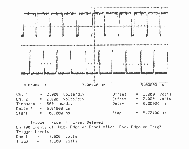
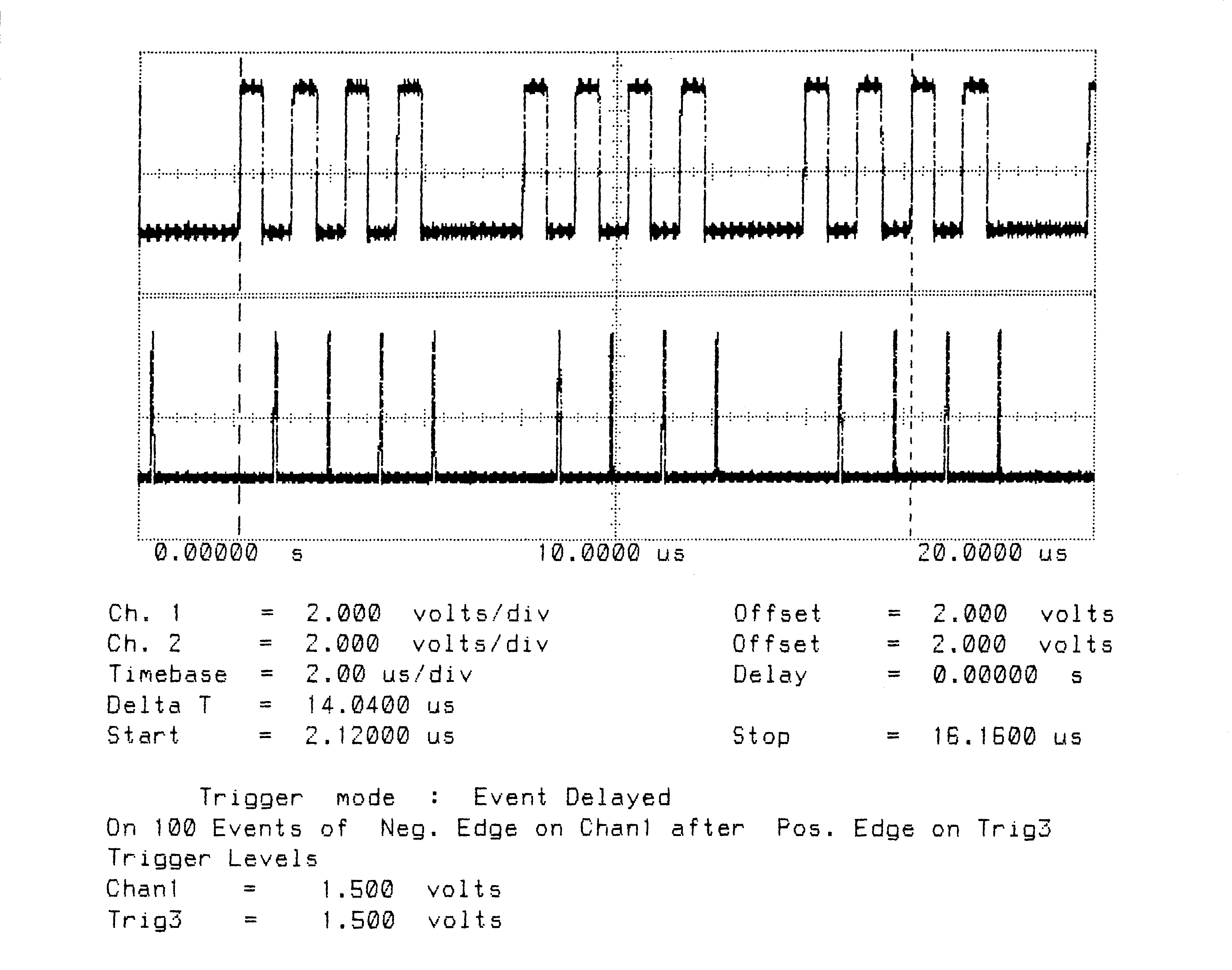
Figures 1 to 10 are oscillographs made with a Hewlett-Packard HP541101GHz bandwidth digitizing sampling oscilloscope. Figures 1 to 5 show an IMS T800B-20 which has link 2 connected to link 3, and the effect of memory cycle time on unidirectional and bidirectional data rate. Similarly, figures 6 to 10 show an IMS T414B20 which has link 2 connected to link 3, and the effect of memory cycle time on link data rate.
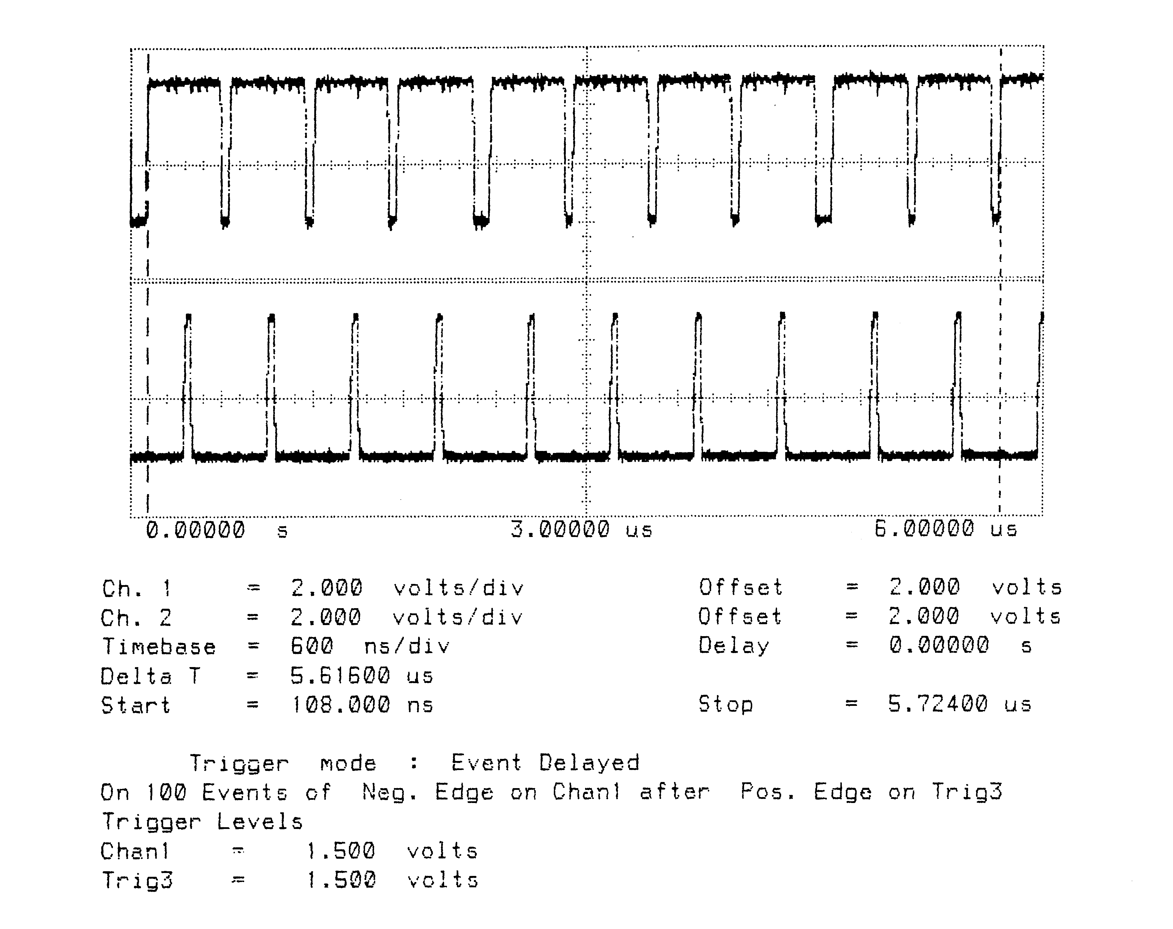
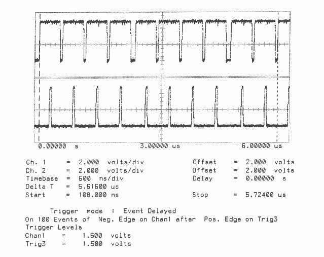
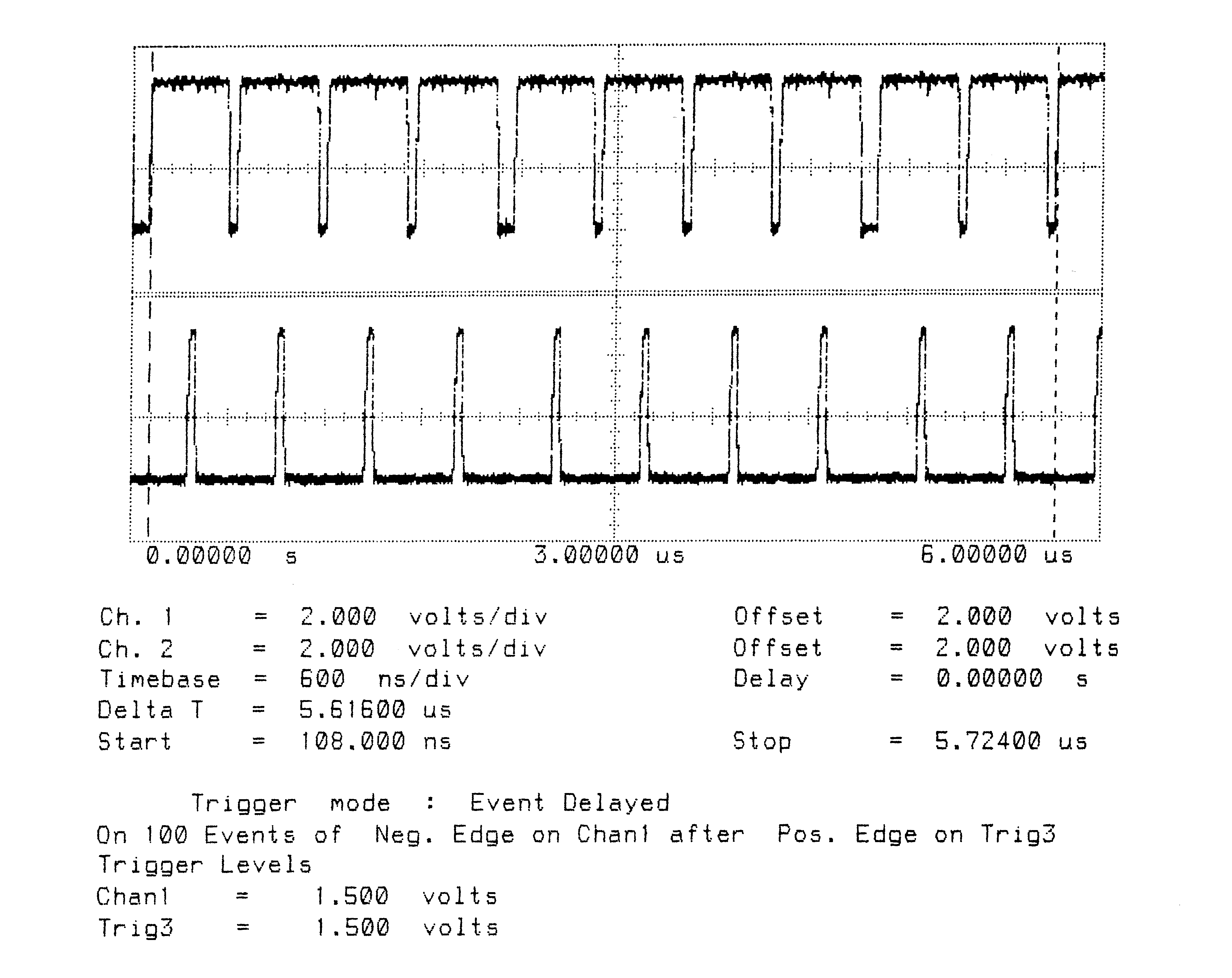
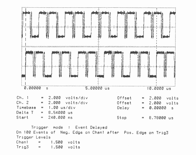
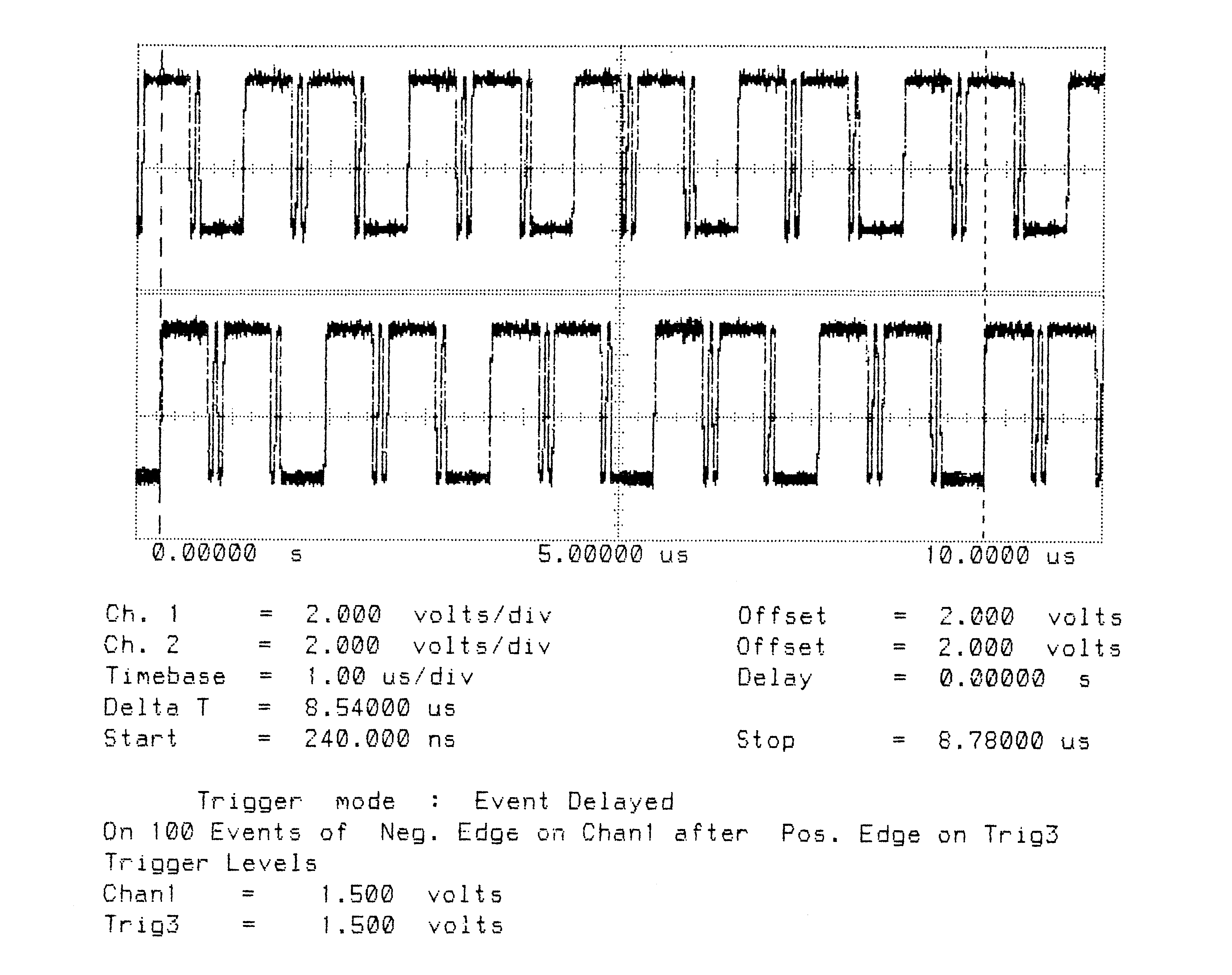
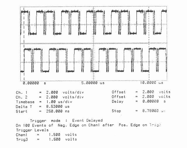
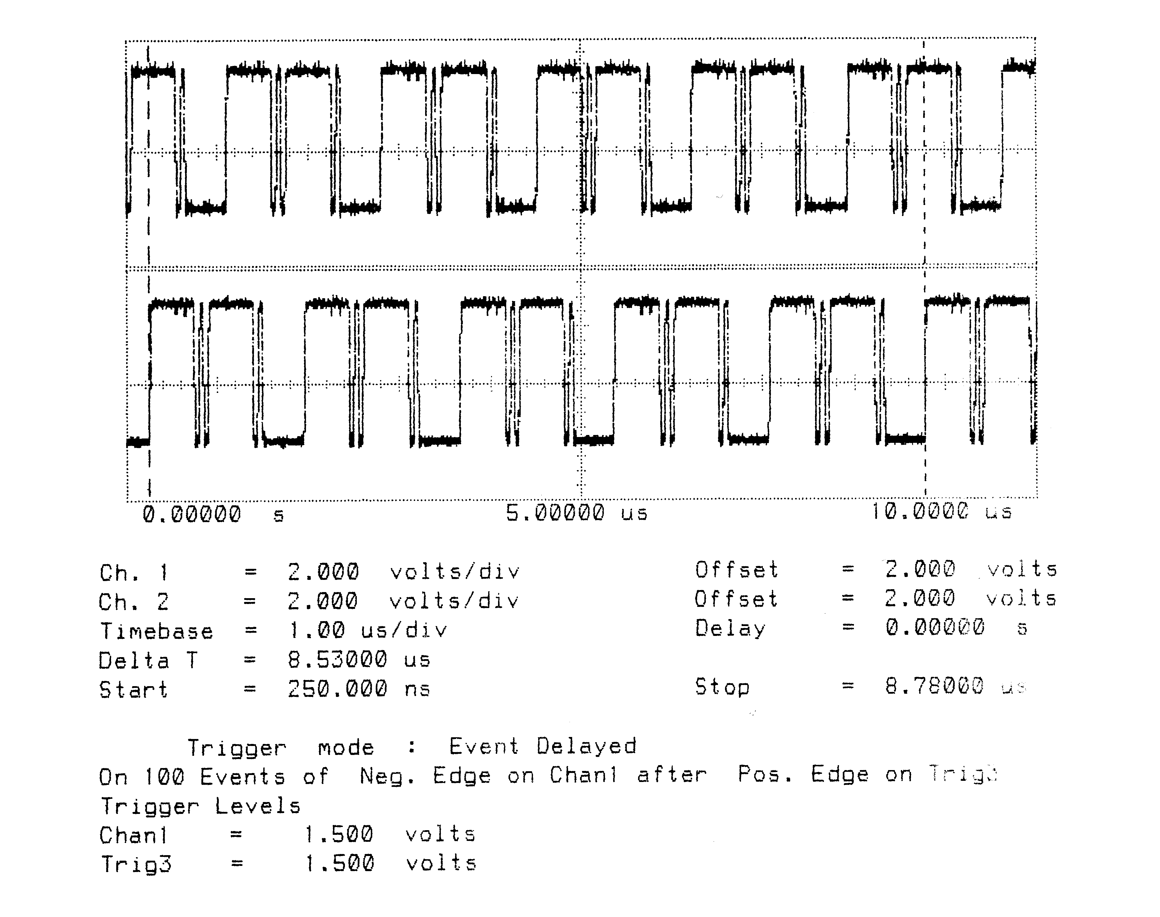
The transputers were booted down link 0. All links were set to operate at 20 MBits/sec, while the transputers were operated at a voltage of 5V and ambient temperature. The data sent in all cases was #FF, being held as a source table in internal memory. The received data was also written by the links into internal memory. Link 0 was not used after booting the transputer, while link 1 was connected back to itself (link 1 output connected to link 1 input). Link 2 was connected to link 3. The same data was output on links 1, 2, and 3. Link 2 output was displayed on the upper part of each oscillograph, and link 3 output was displayed on the lower part. While link data transfers were taking place, the processor was performing a byte slice assignment (block move) from external memory to external memory. The processor was therefore using the maximum memory bandwidth possible while the links were active.
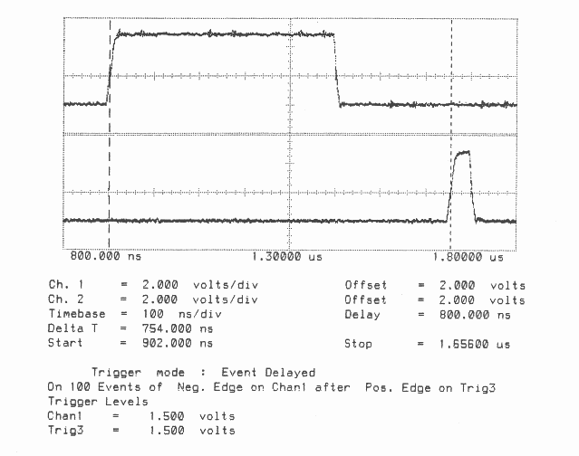
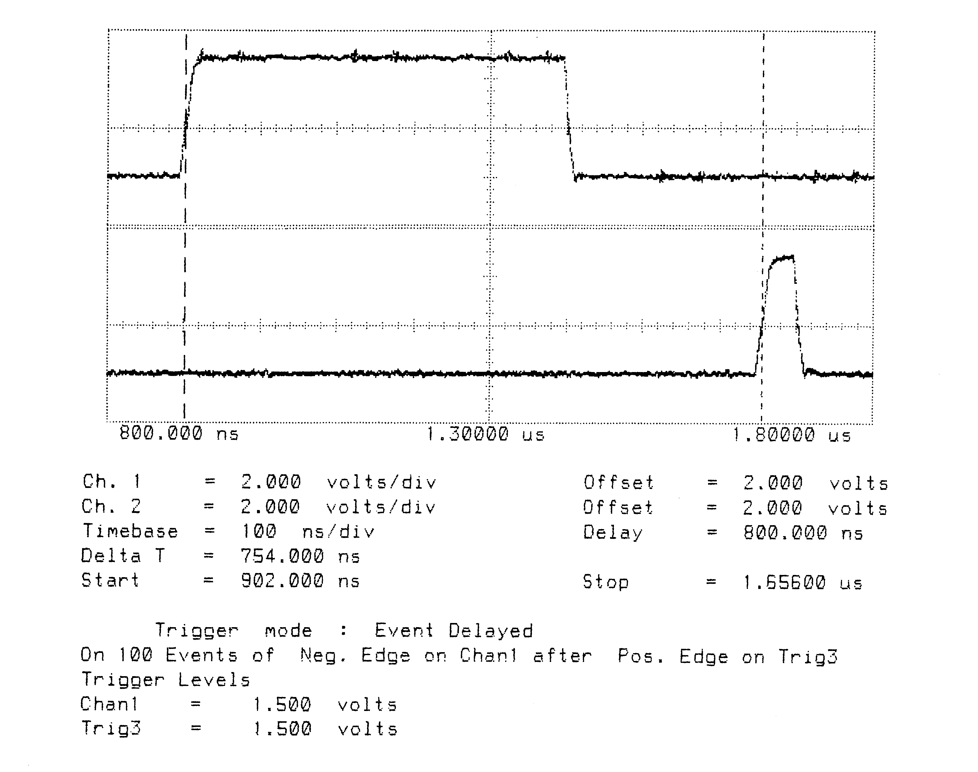
The data packet #FF appears as a logic 1 level on the links for 10 bit periods (500 nsecs). The data packets can therefore be easily distinguished from acknowledge packets which appear as a logic 1 level for one bit period (50 nsecs).
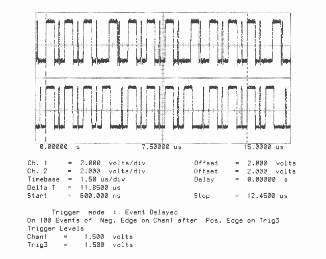
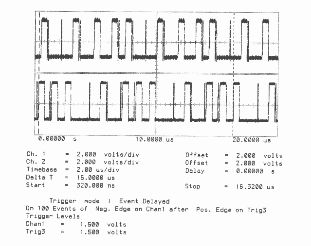
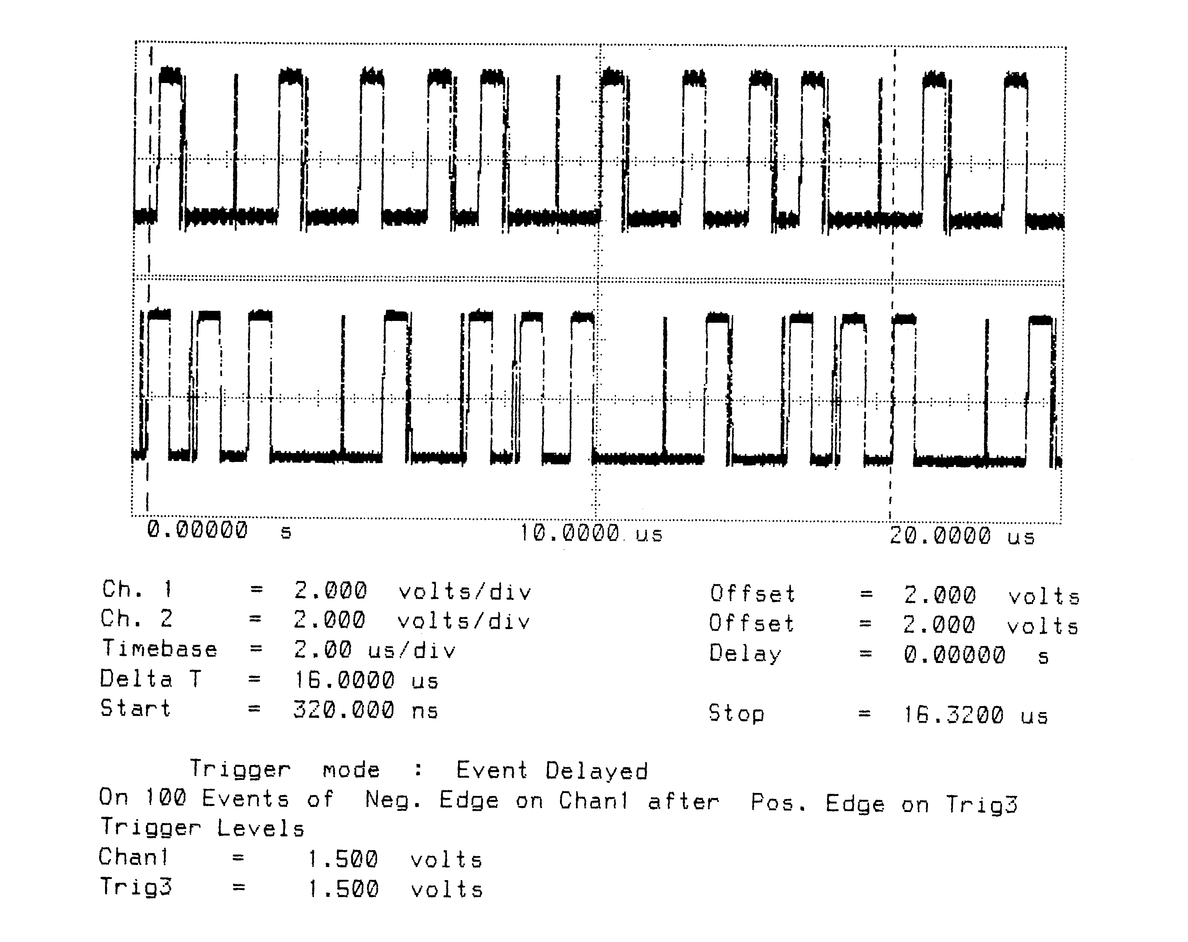
Two programs were run; in figures 1 to 3 and 6 to 8 the data transfer is unidirectional, from link 2 to link 3, while figures 4 to 5 and 9 to 10 the data transfer is bidirectional, between link 2 and link 3.
It can be seen in figure 1 that on the IMS T800 the acknowledge is output, approximately, during the reception of the fifth bit of the eleven bits of a data packet. This allows enough time for the outputting link to prepare to output the next byte while completing the output of the current byte. However, figure 6 shows that on the IMS T414B the acknowledge is only output about fifteen bit periods after the start bit of the data packet is received.
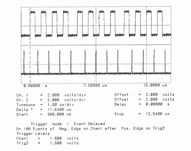
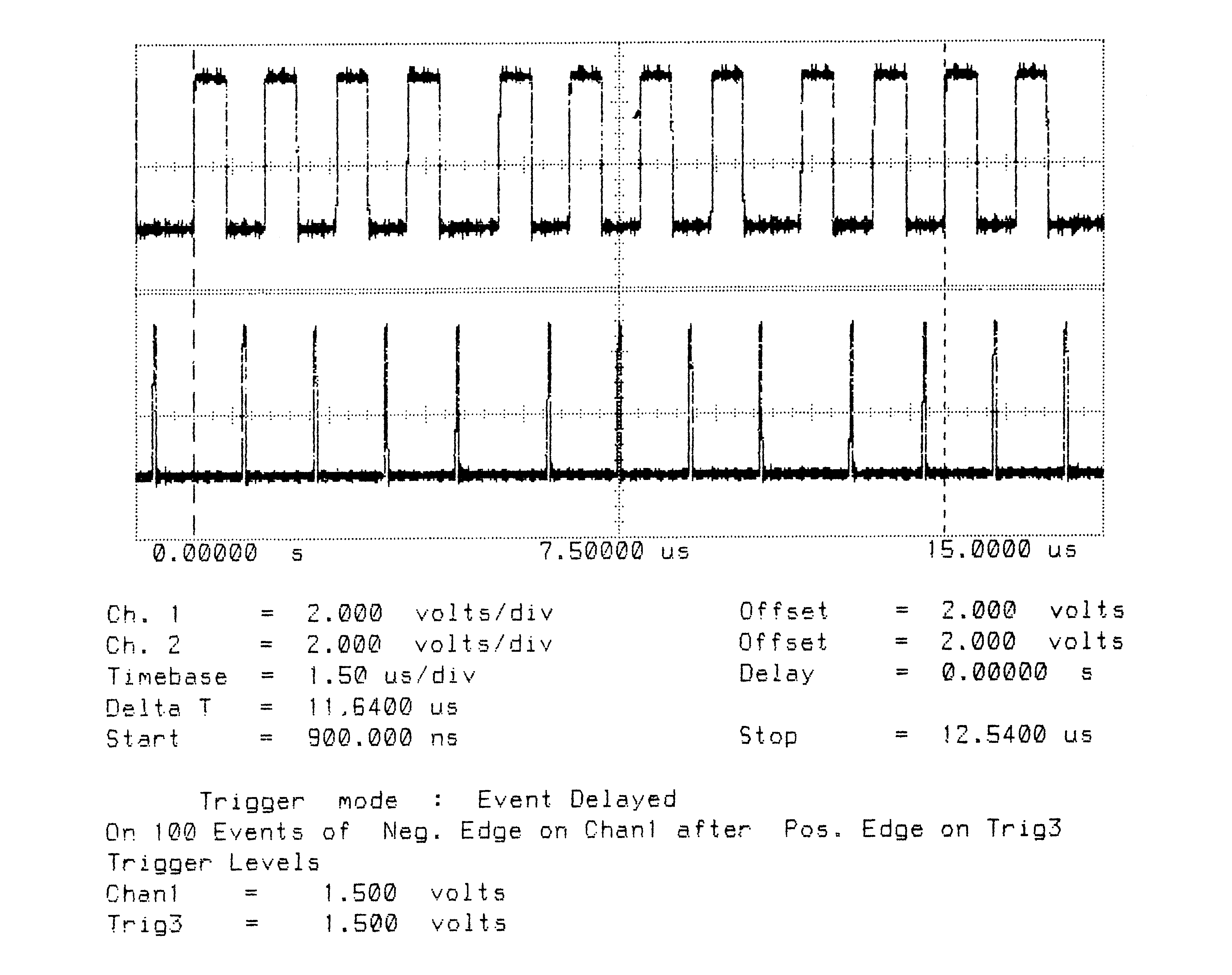
Figures 2 to 5 show ten bytes being transmitted on the IMS T800; this number of bytes allows an accurate calculation of the data throughput of the links to be made. There is no effect of memory speed on the sustained link throughput rate.
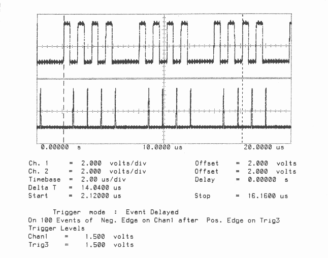
It can be seen in figures 7 to 10 that on the IMS T414B the delay between every four bytes is increased as the memory cycle time is increased, because the next word of data to be transmitted is fetched from memory. Again, these figures show ten bytes being transmitted on the IMS T414B to allow an accurate calculation of the sustained data throughput of the links to be made.
The following table summarises the results obtained.
| Device | Store | Data | Total Bandwidth |
| Type | Cycles | Transfer | on 4 links |
| IMS T800-20 | 3 | Unidirectional | 7.1 MBytes/sec |
| IMS T800-20 | 9 | Unidirectional | 7.1 MBytes/sec |
| IMS T800-20 | 3 | Bidirectional | 9.4 MBytes/sec |
| IMS T800-20 | 9 | Bidirectional | 9.4 MBytes/sec |
| IMS T414B-20 | 3 | Unidirectional | 3.4 MBytes/sec |
| IMS T414B-20 | 9 | Unidirectional | 2.8 MBytes/sec |
| IMS T414B-20 | 3 | Bidirectional | 6.8 MBytes/sec |
| IMS T414B-20 | 9 | Bidirectional | 5.0 MBytes/sec |
By studying the two sets of figures (1 to 5 for the IMS T800, 6 to 10 for the IMS T414B) it can be seen that the data transfer rate is significantly faster on the IMS T800 than on the IMS T414B. The effect of overlapped acknowledges is to allow bytes to be output one after the other, without a significant gap between bytes. The access time of the external memory does not have any effect on the throughput as long as it is smaller than the value which provides enough bandwidth for the processor and links on the IMS T800. It has a direct effect on the throughput on the IMS T414B, adding 50 nsec for every extra memory cycle added to the memory access time, by adding an extra cycle time to the gap between every four bytes (the time taken for a link to read a word from memory).
T800B-20 3 Cycle Store
Vcc = 5V 25∘C Clockln = 5 MHz
Link 2 Connected to Link 3 20 MBits/sec
Delta T is Time from Start of Data to Start of Acknowledge
T800B-20 3 Cycle Store
Vcc = 5V 25∘C Clockln = 5 MHz
Link 2 Connected to Link 3 20 MBits/sec
Delta T is Time for Ten Bytes to be Transmitted from Link 2
Total Bandwidth (4 links) = 7.1 MBytes/sec
Unidirectional
T800B-20 9 Cycle Store
Vcc = 5V 25∘C Clockln = 5 MHz
Link 2 Connected to Link 3 20 MBits/sec
Delta T is Time for Ten Bytes to be Transmitted from Link 2
Total Bandwidth (4 links) = 7.1 MBytes/sec
Unidirectional
T800B-20 3 Cycle Store
Vcc = 5V 25∘C Clockln = 5 MHz
Link 2 Connected to Link 3 20 MBits/sec
Delta T is Time for Ten Bytes to be Transmitted from Link 3
Total Bandwidth (4 links) = 9.4 MBytes/sec
Bidirectional
T800B-20 9 Cycle Store
Vcc = 5V 25∘C Clockln = 5 MHz
Link 2 Connected to Link 3 20 MBits/sec
Delta T is Time for Ten Bytes to be Transmitted from Link 3
Total Bandwidth (4 links) = 9.4 MBytes/sec
Bidirectional
T414B-20 3 Cycle Store
Vcc = 5V 25∘C Clockln = 5 MHz
Link 2 Connected to Link 3 20 MBits/sec
Delta T is Time from Start of Data to Start of Acknowledge
T414B-20 3 Cycle Store
Vcc = 5V 25∘C Clockln = 5 MHz
Link 2 Connected to Link 3 20 MBits/sec
Delta T is Time for Ten Bytes to be Transmitted from Link 2
Total Bandwidth (4 links) = 3.4 MBytes/sec
Unidirectional
T414B-20 9 Cycle Store
Vcc = 5V 25∘C Clockln = 5 MHz
Link 2 Connected to Link 3 20 MBits/sec
Delta T is Time for Ten Bytes to be Transmitted from Link 2
Total Bandwidth (4 links) = 2.8 MBytes/sec
Unidirectional
T414B-20 3 Cycle Store
Vcc = 5V 25∘C Clockln = 5 MHz
Link 2 Connected to Link 3 20 MBits/sec
Delta T is Time for Ten Bytes to be Transmitted from Link 3
Total Bandwidth (4 links) = 6.8 MBytes/sec
Bidirectional
T414B-20 9 Cycle Store
Vcc = 5V 25∘C Clockln = 5 MHz
Link 2 Connected to Link 3 20 MBits/sec
Delta T is Time for Ten Bytes to be Transmitted from Link 3
Total Bandwidth (4 links) = 5.0 MBytes/sec
Bidirectional